ROS Group 产品服务
Product Service 开源代码库
Github 官网
Official website 技术交流
Technological exchanges 激光雷达
LIDAR ROS教程
ROS Tourials 深度学习
Deep Learning 机器视觉
Computer Vision
frank 发布的帖子
-
泓迅科技研发第三代DNA合成技术,要实现成本“超摩尔定律”下降发布在 行业动态
原文出处:http://36kr.com/p/5050118.html
在新一代疫苗生产、大分子药物研发、以生物学为基础的绿色制造、碳源能源可持续转化、环境污染的生物治理、检测有毒化学物质的生物传感器等领域,合成生物学有着广阔的应用前景。作为近年才出现的交叉学科,合成生物学正在对我们的健康和全球环境正产生巨大影响,或许会成为下一个爆发点。
然而,合成生物学产业的发展目前急需解决一项关键问题——合成基因的成本与通量。新一代DNA合成技术,有望凭借其高通量、低成本的优势给该产业带来新的突破。目前,全球范围内拥有此项技术的只有美国的Twist Bioscience 和Gen9等少数公司。在国内,成立于2013年的苏州泓迅生物科技有限公司,正努力新一代DNA合成技术设计和应用方面进行探索。
泓迅科技专注开发新一代DNA“读-写-编”技术,目前已建立起全球领先的“GPS”技术平台。该平台依据生命科学最核心的中心法则,在基因型“G”(Genotype)、表型“P”(Phenotype)基础上引入了人工合成型“S”(Synotype),并将三者有机的结合在一起。
依托自主开发的Syno
 合成技术系列专利组,公司提供快速、高效和专业的基因技术服务,以满足诸如人源化抗体库构建、基因工程疫苗开发、工业酶优化、染色体/基因组合成、分子辅助育种以及数字化信息转化为DNA及存储技术开发等不同应用领域的需求。
泓迅科技商务副总裁刁文一表示,泓迅科技高通量、低成本的新一代Syno
 3.0 DNA合成技术,能够使DNA合成成本下降至原来的三分之一甚至更多,实现合成成本的“超摩尔定律”的下降 。在此基础之上,泓迅科技正在推动新一代DNA合成技术面向生物医药、新能源、作物育种和信息技术等多个领域的应用转化,目前已经为包括塞默飞、华大基因、清华大学、天津大学等在内的数百家跨国药企、生物技术公司、高校及科研院提供DNA“设计—创建—应用”一体化解决方案。
对于商业模式的考虑,刁文一表示,泓迅科技前期主要是为相关公司与科研机构提供基于科研外包服务,通过高标准的“生产力”输出,检验科技先进性,跑赢市场预期。 公司未来发展方向还是着眼于进一步拓展以DNA技术为依托的设计和应用市场。
泓迅科技创始人杨平博士,有多年的研发管理经验及国际化商业成功的案例,参与“863”和“973”合成生物学重大专项的专家顾问,参与“十三五”合成生物学重大专项基因合成平台的设计。核心管理团队累计有50年以上的合成生物学行业经验,拥有丰富的技术研发、产业化管理及营销经验和实力。凭借丰富的DNA合成经验,团队核心成员曾在埃博拉,H7N9,寨卡病毒的诊断、治疗、预防等科研工作中做出重要科研贡献。
2014年,泓迅科技曾获得华大科技A轮战略投资 。泓迅科技近期已经完成B轮融资,该轮投资由凯风创投、协立投资与雅惠精准医疗基金共同投资。此轮融资后,泓迅科技将继续着重于Syno
 1.0、2.0、3.0等合成平台的持续优化,Syno
 3.5自动化高通量合成技术的研发、以及“GPS”平台的完善,旨在成为领先的DNA技术及合成生物学公司。
 -
“镭神智能”获近亿元A轮融资,招商资本领投,近期目标是实现激光雷达量产发布在 行业动态
本文转至http://36kr.com/p/5050163.html
近日,我们之前报道的“镭神智能”宣布获得近亿元的A轮融资,招商资本领投,如山资本跟投。天使轮投资方北极光创投在A轮继续跟投。镭神智能将会利用本轮融资进一步扩大规模、加强人才引进、建立软件研发中心、完善自动化生产基地。近期发展目标是实现专业激光雷达量产,并批量销往海外。
镭神智能成立于2015年初,目前累计融资总额为1亿元,提供机器人导航避障激光雷达、激光灭蚊炮和激光灭蚊机器人、激光成像雷达、无人驾驶激光防撞雷达、无人机定高激光雷达、激光扫描仪、位移传感器、特种光纤激光器等产品及解决方案。
镭神智能的激光雷达系列产品中,用于扫地机器人及服务机器人的激光雷达已经投入量产。具有非旋转扫描测距激光雷达,适用于无人机定高、工业自动化等领域。基于时间飞行法测距原理的单线激光雷达系列产品,已经研发成功。此外镭神智能还有自主研发的多线激光雷达、高端三维地形测绘系列激光雷达以及全固态相控阵系列激光雷达等。
在汽车雷达方面,目前镭神智能的中远距离脉冲测距激光雷达系统测量距离为200米,可用于汽车防撞、无人机自主导航避障、无人驾驶汽车等。
具体参数方面,这款雷达可以进行360全方位扫描(非固态),扫描半径为100米,测量精度0.3米,扫描频率为10-20Hz,每秒最高可测量2000点,同时,胡小波告诉我,由于这种雷达是不断在人眼高度范围内进行横向发射,因此需要严格限制激光功率,以确保人眼安全。
镭神智能创始人胡小波于2002年接触激光雷达,2004年创办了“创鑫激光”,最初代理国外的光纤激光器,当时做的是峰值功率较高的雷达,测量距离远、最初用于直升机、飞机上的地貌测绘,价格也较高。
-
让ubuntu普通用户支持不输密码直接shutdown命令关机发布在 技术交流
修改/etc/sudoers文件
sudo gedit /etc/sudoers
#然后增加下列指令
%xiaoqiang ALL = NOPASSWD: /sbin/shutdown  #将xiaoqiang换成自己的用户名
#保存后退出
现在可以关机试试
sudo shutdown -h now会发现不用输密码了
-
小强ROS机器人教程(19)___NLlinepatrol_planner的简单使用发布在 产品服务
随小车主机附带的NLlinepatrol_planner是一个用于视觉导航的全局路径规划器,根据小车输出的视觉轨迹,能输出一条连接小车当前坐标和目的坐标的全局路径,下文将通过一个模拟实例来演示它的使用方式。主要思路是:一个python脚本发布虚拟的视觉里程计和相关tf树,一个python脚本给move_base节点发布目标点,最后move_base节点通过调用NLlinepatrol_planner获得一条全局路径并在rviz中显示。
1.配置NLlinepatrol_planner
需要提供NLlinepatrol_planner待读取的视觉轨迹文件、轨迹坐标变换需要的变换参数文件,这两文件都应该放在NLlinepatrol_planner下面的data文件夹内,文件名任意,通过配置move_base中的相关参数可以指定NLlinepatrol_planner读取的文件,下文会说明。

在上图中,nav1.csv是视觉轨迹文件、TFSettings.txt为变换参数文件(第一行是旋转矩阵的9个元素、数组元素排列顺序为c语言的行排列,第二行为平移向量的xyz分量,第三行为scale因子)
2.制作move_base的launch文件
对于本教程,我们已经在nav_test软件包中的launch文件夹内提供了相关的launch文件,名字为xq_move_base_blank_map2.launch,这个launch文件在实际运用时可以作为模板,需要注意的地方请看下图

这个launch文件会调用xq_move_base2.launch文件,xq_move_base2.launch文件也在当前目录下,里面的内容如下<launch> <node pkg="move_base" type="move_base" respawn="false" name="move_base" output="screen"> <param name="base_global_planner" value="NLlinepatrol_planner/NLlinepatrolPlanner"/> <rosparam file="$(find nav_test)/config/NLlinepatrol/costmap_common_params.yaml" command="load" ns="global_costmap" /> <rosparam file="$(find nav_test)/config/NLlinepatrol/costmap_common_params.yaml" command="load" ns="local_costmap" /> <rosparam file="$(find nav_test)/config/NLlinepatrol/local_costmap_params.yaml" command="load" /> <rosparam file="$(find nav_test)/config/NLlinepatrol/global_costmap_params.yaml" command="load" /> <rosparam file="$(find nav_test)/config/NLlinepatrol/base_local_planner_params.yaml" command="load" /> <rosparam file="$(find nav_test)/config/NLlinepatrol/base_global_planner_params.yaml" command="load" /> </node> </launch>通过上述内容,发现通过设置base_global_planner参数值来指定全局路径规划器为NLlinepatrol_planner,还可以看出move_base的其它参数配置文件放在nav_test软件包内的config/NLlinepatrol路径内

对于上图,我们需要更改的文件是base_global_planner_params.yaml,因为这个文件里的内容对应NLlinepatrol_planner运行时实际加载的参数,默认内容如下
NLlinepatrolPlanner:
    DumpFileName: AnnDump.sav
    strTFParsFile: TFSettings.txt
    TxtFileName: nav1.csv
    ANN_Dump_Bool: false
    connect_distance: 0.3
TxtFileName是加载的视觉轨迹文件名,strTFParsFile是加载的变换参数文件名,connect_distance设置视觉轨迹文件中连通点之间的最大距离(坐标变换后两个点之间的距离小于该值就认为这两点之间没有障碍物,可以直接连接),ANN_Dump_Bool值为false表示从txt文件中加载轨迹和变换参数、如果为true则从DumpFileName参数指定的dump文件加载(多次使用同一个视觉轨迹文件时,第二次以后从dump文件启动可以加速)
3.配置完成开始使用
A.因为我们这次是虚拟运行,发布的一些topic是没有实际意义的但是和小强默认ROS驱动冲突,所以现在需要停止所有ROS运行实例
sudo service startup stop
roscore
B.启动虚拟topic和小强模型文件
rosrun orb_init temp.py //发布odom
roslaunch xiaoqiang_udrf xiaoqiang_udrf.launch //启动模型
C.启动上文制作的xq_move_base_blank_map2.launch文件
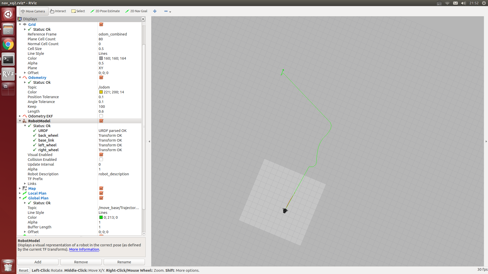
roslaunch nav_test xq_move_base_blank_map2.launchD.启动rviz,并打开ros/src/nav_test/config/nav_xq2.rviz配置文件
rvizE.启动虚拟goal发布节点(基于惯性导航中的squre.py修改而来)
rosrun nav_test NLlinepatrol.py4.现在rviz中就已经出现目标全局路径轨迹了(绿线),想测试其它goal目标点,请自行修改NLlinepatrol.py中相关代码
-
微软开源Malmo项目:允许任何人在Minecraft(游戏)中测试自己的AI作品发布在 行业动态
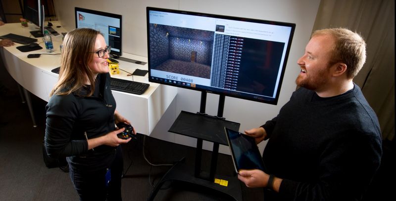
最终,开发者总算可以在Minecraft(一款游戏)中实现人工智能方面的创作自由了。昨日(7月9日),微软正式宣布开源Malmo项目(公司用于Minecraft中的AI软件测试系统),表示任何人都能参与进来测试AI软件。这一平台的设计目的是向创业公司提供廉价、有效的方式来测试人工智能程序,使它们不必再开发新的机器人去操控实体对象。
此外, Malmo还可用于“强化学习”,即让人工智能程序通过反复尝试和试错去学习并做出正确的选择。
其实早在今年3月,微软就首次将系统开放给科研人员,那时该系统的名字为AIX。但本次声明则意味着Malmo的所有代码将免费向公众开放。所有代码可在Github中的开源许可协议基础上获得,包括如何在嵌入的平台上部署脚本的完整教程。
这样做的结果显然与典型的AI测试(在一个测试环境中对代码进行部署与监测)会有很大的不同。但科研人员希望能够用Minecraft代替以前的测试环境,在此基础上得出关于各种AI 脚本运行能力与局限性的新结论。既然典型的Minecraft环境与大多数AI测试环境有较大的差距,微软希望通过此次开源来加速解决AI开发中的各种问题,特别是导航任务。
“这将对教育领域产生影响,至少是在大学范围内,”Malmo项目的负责人Matthew Johnson在声明中指出,“如果我打开一些YouTube视频,碰巧这些视频新增加的功能是由我们的模组实现的,那么我会兴奋上一整天。”
来源出处:http://36kr.com/p/5049290.html
-
波罗 11 号的源代码现在可到 GitHub 查看了发布在 行业动态
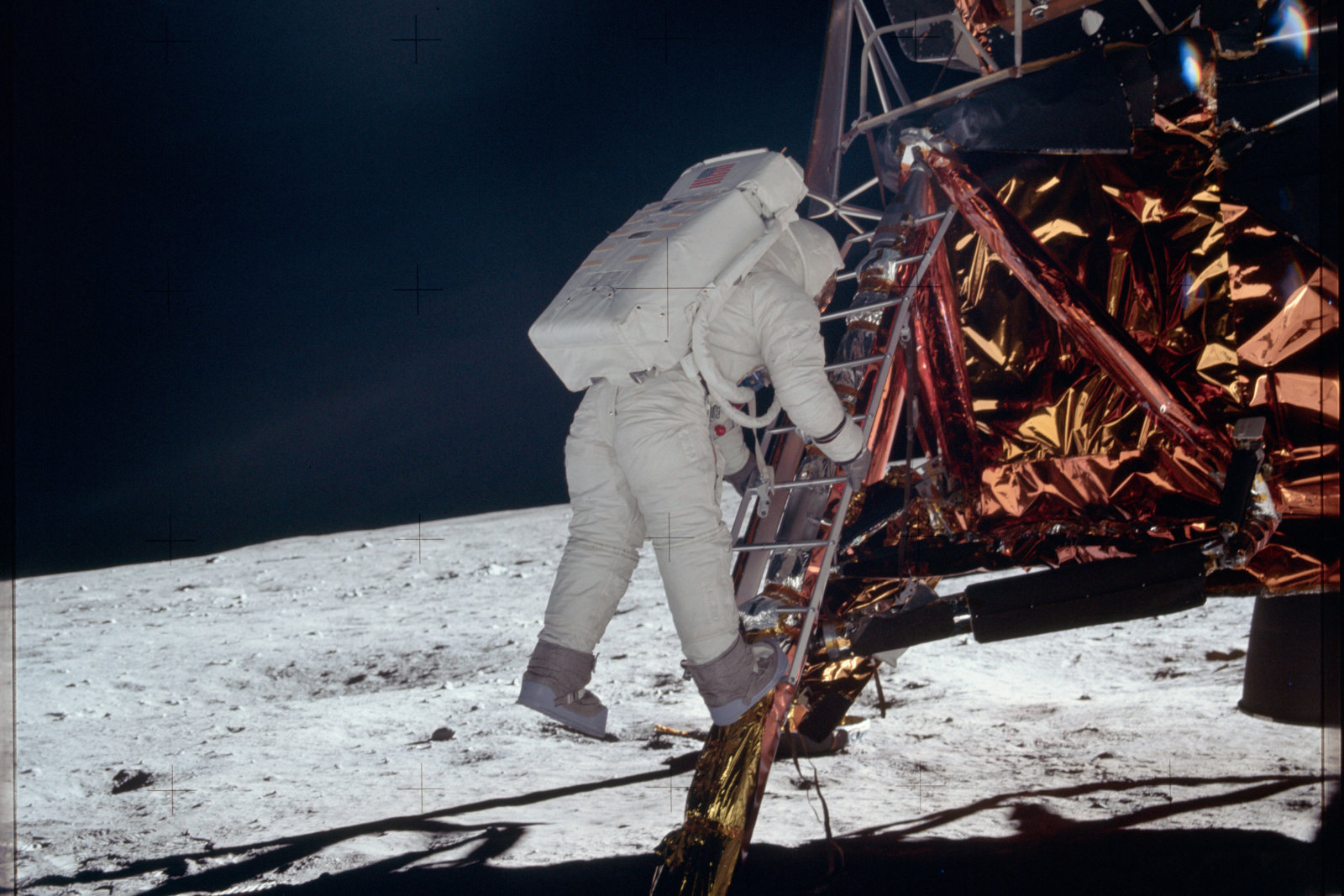
协助人类历史迈出一大步的登月器阿波罗 11 号,到底它的制导电脑所用的软件是怎么样呢?这曾经由谷歌保管的源代码,前 NASA 实习生 Chris Garry 张贴在 GitHub 上公开予所有人,让公众都可以得知 NASA 编写的登月制导程序是如何的。先不论代码的优劣,但 Reddit 使用者就指编程员是个幽默的人,因为源代码线的第 666 行藏着「numero mysterioso(神秘代号)」的彩蛋,而且还有为「burn, baby, burn」的代码下了一整段的引用来源呢。有趣的是,根据 Quartz 的说法,编程员更可以为这 GitHub 贴文提出建议,当中更不乏阿波罗 13 号的笑话… 虽说这段源代码并不可能帮助大家重现阿波罗计划,但也是一个有趣的角度来让大家知道这有着重大历史意义的事件。
本文来源:http://www.tuicool.com/articles/zaQBFn2 -
ubuntu14.04升级cmake版本后,ROS catkin_make错误解决办法发布在 技术交流
ubuntu默认安装的cmake版本是2.X的,有时候编译某些软件时需要升级到3.x以上。
如果是手动源码编译升级方式,可能会导致cmake的安装路径与开始的安装路径不一致(通常是/usr/bin/cmake 与/usr/local/bin/camke的区别),不利后果就是升级完后在之前的ROS工作空间使用catkin_make命令会发生如下错误:
####
make: /usr/bin/cmake: Command not found
make: *** [cmake_check_build_system] Error 127
Invoking "make cmake_check_build_system" failed
解决办法如下
1.删除ROS工作空间src文件夹下的CMakeLists.txt文件
2.重新运行下述命令重置ROS工作空间(放心,不会删除src文件内的内容,哈哈)catkin_init_workspace3.删除ROS工作空间中的build文件夹
4.重新运行catkin_make命令,问题解决,遗憾的是之前的项目全部会重新编译 -
小强ROS机器人教程(8)___kinect1代 ROS驱动测试与安装发布在 产品服务
小强底盘输出一个12v电源(DC头,贴有“kinect供电”标签)用于kinect 供电。
1.libfreenect测试
将小强主机接入显示器和键盘,在小强主机上新开一个命令终端输入
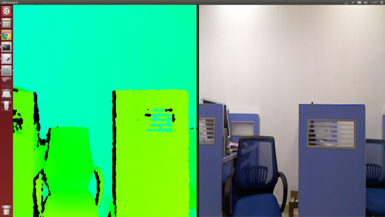
freenect-glview可以看到如下图的类似界面
2.ROS驱动测试
关闭步骤1中的程序,新开一个命令窗口,使用freenect_launch启动相关kinect节点
roslaunch freenect_launch freenect-xyz.launch新开1个窗口打开rviz
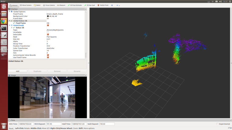
rviz选择需要显示的内容,例如kinect的rgb图像和深度点云,显示效果如下
kienct各项功能的开启在/home/xiaoqiang/Documents/ros/src/freenect_stack/freenect_launch/launch/examples/freenect-xyz.launch里面<launch> <include file="$(find freenect_launch)/launch/freenect.launch"> <arg name="camera" value="kinect" /> <arg name="motor_processing" value="true" /> <arg name="audio_processing" value="false" /> <arg name="rgb_processing" value="true" /> <arg name="ir_processing" value="false" /> <arg name="depth_processing" value="true" /> <arg name="depth_registered_processing" value="false" /> <arg name="disparity_processing" value="false" /> <arg name="disparity_registered_processing" value="false" /> <arg name="num_worker_threads" value="4" /> </include> </launch>通过设置true 或者false来开启、关闭相应功能
3.下文将介绍kienct1代的ros驱动安装步骤
2016年7月以后购买的用户不需要安装驱动,小强主机已经配置好kinect 1代驱动。
需要安装三个软件:
a.libfreenect
b.rgbd_launch
c.freenect_stacka. libfreenect
先将kinect接入小强主机,然后打开一个命令行终端,输入下列代码
cd Documents

sudo apt-get install git-core cmake freeglut3-dev pkg-config build-essential libxmu-dev libxi-dev libusb-1.0-0-dev

git clone https://github.com/OpenKinect/libfreenect
cd libfreenect
mkdir build
cd build

# 重点来了,下面配置将使能kinect音频和解决安装路径问题
cmake .. -DCMAKE_INSTALL_RPATH:STRING="/usr/local/bin;/usr/local/lib" -DBUILD_REDIST_PACKAGE=OFF

make
sudo make install
sudo ldconfig /usr/local/lib64/
sudo freenect-glview
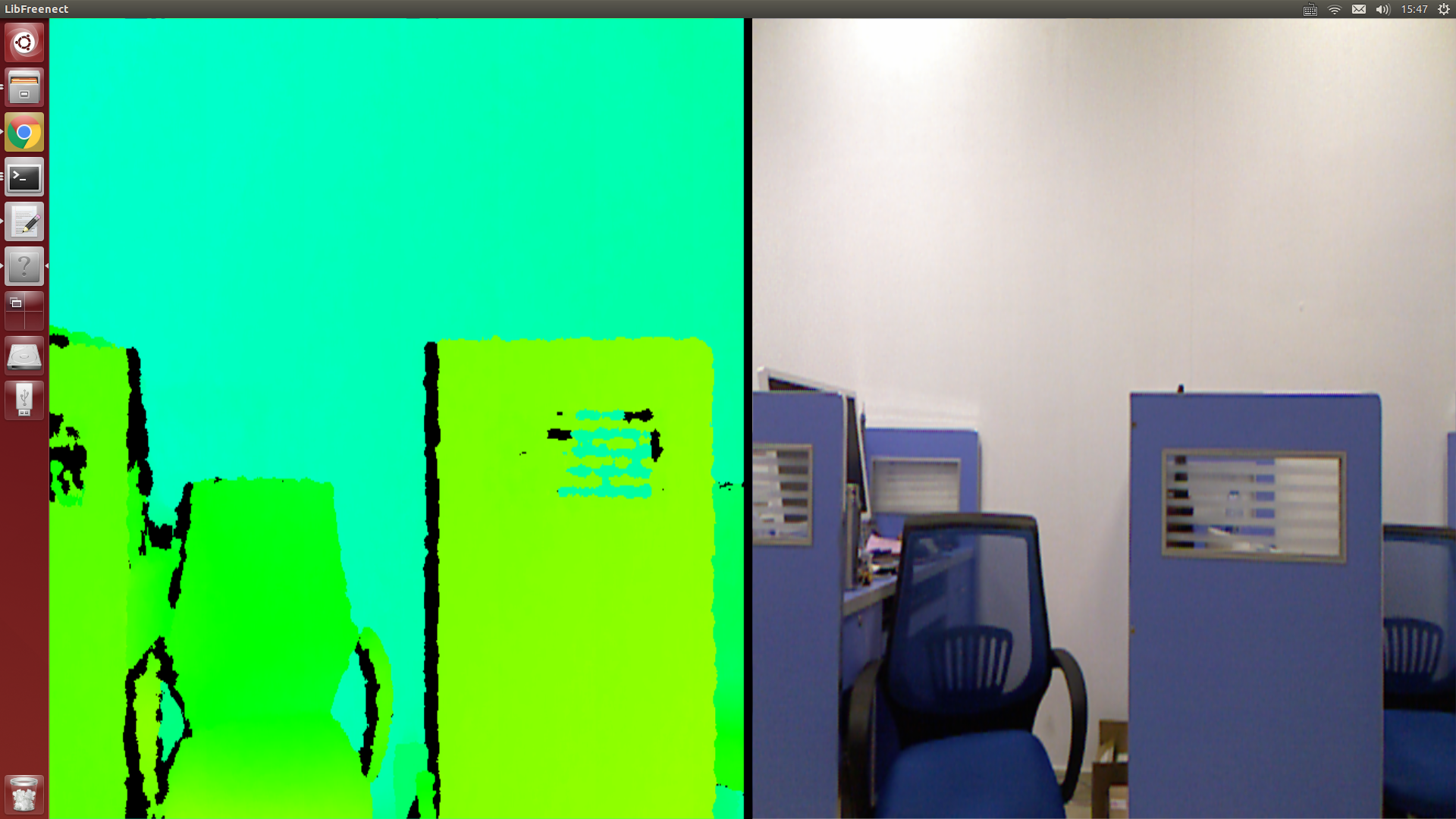
现在应该可以看到kinect的输出图像了
再进行外设权限配置操作sudo adduser $xiaoqiang video //请将xiaoqiang换成自己电脑的账户名增加一个udev规则,先打开51-kinect.rules文件
sudo gedit /etc/udev/rules.d/51-kinect.rules拷贝如下内容后保存退出
# ATTR{product}=="Xbox NUI Motor"
SUBSYSTEM=="usb", ATTR{idVendor}=="045e", ATTR{idProduct}=="02b0", MODE="0666"
# ATTR{product}=="Xbox NUI Audio"
SUBSYSTEM=="usb", ATTR{idVendor}=="045e", ATTR{idProduct}=="02ad", MODE="0666"
# ATTR{product}=="Xbox NUI Camera"
SUBSYSTEM=="usb", ATTR{idVendor}=="045e", ATTR{idProduct}=="02ae", MODE="0666"
# ATTR{product}=="Xbox NUI Motor"
SUBSYSTEM=="usb", ATTR{idVendor}=="045e", ATTR{idProduct}=="02c2", MODE="0666"
# ATTR{product}=="Xbox NUI Motor"
SUBSYSTEM=="usb", ATTR{idVendor}=="045e", ATTR{idProduct}=="02be", MODE="0666"
# ATTR{product}=="Xbox NUI Motor"
SUBSYSTEM=="usb", ATTR{idVendor}=="045e", ATTR{idProduct}=="02bf", MODE="0666"
注销用户后重进系统,现在就能直接启用kinect了,不用sudo了
freenect-glviewb. 安装rgbd_launch
rgbd_launch包含了驱动安装包openni_launch或 freenect_launch需要的通用launch文件。
主要有两个重要的launch文件:- processing.launch.xml:安装一系列nodelets去处理来自RGB-D driver(openni_camera or freenect_camera的数据,还可以设定参数简化处理nodelets图像。
- kinect_frames.launch:为 Kinect安装tf tree。也可以从openni_launch or freenect_launch内部启动该文件。
rgbd_launch文件包含多个分散处理的launch文件。但只有 processing.launch.xml可以在外部修改使用。
cd ~/Documents/ros/src
git clone  https://git.bwbot.org/publish/rgbd_launch
cd ..
catkin_make
c. 安装freenect_stack
cd ~/Documents/ros/src
git clone  https://gitee.com/BlueWhaleRobot/freenect_stack
cd ..
catkin_make
d. 驱动安装完成,现在可以在ROS中使用kinect了,例如在rviz中观看kinect输出的点云,参考本节开头的步骤2
-
美国警方首次采用机器人炸死嫌犯发布在 行业动态
嫌疑人名为迈卡·约翰逊,25岁,非洲裔,达拉斯本地人。他起初从一座建筑中的多个楼层向警方射击,最后在一座停车库内与警方对峙数小时。
警方劝降未果,最终使用一部携带爆炸物的机器人接近约翰逊并引爆炸药,炸死约翰逊。达拉斯警察局长戴维·布朗说:“我们没有别的办法,只有使用炸弹机器人,把炸药放在机械臂上,在嫌疑人藏身的地方引爆。如果采用其他方式,警方人员会置身于非常危险的境地。”新美国基金会专家彼得·辛格说,这是美国警方首次使用作战机器人击毙嫌疑人。
达拉斯警方究竟使用了何种作战机器人击毙嫌疑人约翰逊,外界暂时不得而知。达拉斯警方没有透露关于作战机器人的具体信息。
但据英国《每日邮报》记者调查了解,达拉斯警方爆破小组确实引进过世界第四大军工生产厂商诺斯洛普·格鲁门公 司(Northrop Grumman)生产的遥控机器人F6A或F6B,这两款机器人是警方和军队使用的作战标配装置。据悉,美军在伊拉克战场上曾配备并使用了一款叫做Marcbot的作战机器人。资料显示,达拉斯警察局和邻县邓肯威尔警察局各自拥有一个Marcbot作战机器人。
纽约州警察局退休副局长威廉·弗拉纳根目前担任执法和技术顾问,他推测达拉斯警方可能在作战机器人身上装备了低爆破量的炸药,这种炸药通常是爆破小组用来炸毁嫌疑包裹的。弗拉纳根说,使用这种炸药可以让靠近它的嫌疑人丧失行动能力。
-
新人工智能系统在模拟空战中击败战术专家发布在 行业动态

美国退役空军上校 Gene Lee 在飞行模拟器中与人工智能展开了模拟空战,该人工智能技术的研发团队由工业界、美国空军和辛辛那提大学的代表所组成。美国退役空军上校及军事专家 Gene Lee 是一位有着大量空战经验的指导员,也是一位专业知识丰富的空战指挥官(Air Battle Manager)。最近他通过一个高仿真空战模拟器对辛辛那提大学博士后开发的人工智能进行了测评。
这个被称作 ALPHA 的人工智能在模拟战斗取得了胜利,据 Lee 说,它是「我迄今为止见到的最具侵略性、反应最快、最灵活而且最可靠的人工智能。」
ALPHA 所用的技术中有一项被称作遗传模糊系统( genetic-fuzzy system)的重大突破,它的成功是一项重大突破,相关细节可以参看最新一期的 Journal of Defense Management。这个应用是专门为研究空战演习任务中的无人作战飞机(UCAV)的使用而研制的。
这个被称作 ALPHA 的人工智能在模拟战斗取得了胜利,据 Lee 说,它是「我迄今为止见到的最具侵略性、反应最快、最灵活而且最可靠的人工智能。」
用于研发 ALPHA 的工具和 ALPHA 项目本身都是由 Psibernetix 公司开发的,这家公司的创始人是现任公司总裁兼 CEO 的加州大学工程与应用科学院 2015 届博士 Nick Ernest 以及 Psibernetix 公司程序开发负责人 David Carroll;为该公司提供技术支持的有加州大学航空航天教授 Gene Lee、Kelly Cohen 和博士生 Tim Arnett,资金支持来自于美国空军研究实验室(Air Force Research Laboratory)。
高压和快节奏:人工智能陪练员
ALPHA 目前被视为模拟环境中有人和无人作战配合的研究工具。在它最早期的迭代版本中,ALPHA 就经常超过美国空军实验室之前研究所用的电脑程序的基准水平;换句话说,它打败了其它人工智能对手。
事实上,初代 ALPHA 击败了空军实验室其它计算机对手后不久,Lee 就在去年十月通过手动操作迎战了更成熟的 ALPHA。经过数次尝试后,他不仅无法在对抗 ALPHA 上获得一次击杀得分,而且还每次都在持久对峙后被从空中击落。
自从第一次人类 vs. ALPHA 模拟战斗后,它又连续击败了很多专家。而且即使故意降低了(ALPHA 操控的)飞机的速度、转向灵敏度、导弹能力和传感器后,它仍能打赢人类对手。
Lee 从 1980 年代早期以来就经常在模拟器中与人工智能对手进行飞行对战,他在第一次和 ALPHA 对战后说:「我惊讶于它的高度警惕性和反应灵敏性。它似乎知道我的意图,我每次改变飞行轨迹和导弹部署时它都会迅速做出反应。它知道如何打退我的进攻。它能根据需要在防御和进攻模式间快速切换。」
他还补充道:「与大部分人工智能对战时,一个经验丰富的飞行员是可以打败它们的。当然,如果你尝试一些新策略,可能时不时会被人工智能打下来。但到目前为止,一个人工智能对手是无法跟得上类似战斗情景中的真实压力和紧迫节奏的。」
但是现在,却是与上千美国空军飞行员一起训练过的,开过好几架战斗机,并且从美国作战武器学院(U.S. Fighter Weapons School)毕业(相当于拿到了空战战术战略的高级学位)的Lee感受到ALPHA带来的压力,其它飞行员也是如此。
而且,当 Lee 与 ALPHA 进行了长达几小时的模拟真实任务的战斗后,「我回到家感觉精疲力尽,身心疲惫。这也许只是人工智能,但它代表着一种真正的挑战。」
人工智能僚机:一个人工智能战士会怎样演化
Ernest 解释说,「ALPHA 是你在这些模拟环境中会遇到的致命敌人。我们的目标是继续开发 ALPHA,增强和扩展它的性能,并开展与其他受训飞行员的对战试验。仿真度也需要提高,我们会采用更接近真实的空气动力学和传感器模型。ALPHA 完全有能力适应这些环境,我们 Psibernetix 公司着眼于未来的持续发展。」
从长远来看,将人工智能融合进美国空军战斗力中意味着一次革命性的飞跃。人类飞行员进行空中战斗时需要熟练运用航空物理学知识和相关技艺,还需要灵活调遣高速移动战斗机和对敌导弹的直觉。毕竟,如今的战斗飞行员是以超过每小时 1500 英里的速度在4万英尺以上的高空作战,而且彼此距离很近。每一毫秒都很重要,一旦出错代价会很惨重。
由于 ALPHA 的运行速度已经远远超过了其它基于语言的消费软件产品,它现在的目标就是降低出错概率。事实上,ALPHA 可以获取全部传感器数据,把它们组织起来并绘制出一副完整的战斗场景,并在一毫秒内它就能给一个四架战斗机组成的机群做出或更改战斗决策。由于速度非常快,在动态环境中它能充分考虑和协调最佳战术计划和最精准的响应,而且做出决策的速度比人类对手眨眼还快 250 倍。
未来的空战所需的反应速度已经超出人类能力范围之外,因此会需要集成了人工智能的无人战斗机(UCAV)作为僚机与人类飞行员相配合,机载的战斗管理系统将能够胜任情景感知、决策响应、战术选择、武器管理和使用等工作。像 ALPHA 这样的人工智能可以同时规避几十颗敌方导弹、对多个目标实施精准打击、协调队伍成员的行动、还能通过观察记录和学习敌方的战术和战能力。
加州大学的 Cohen 补充道:「ALPHA 会是一个非常易于合作的人工智能伙伴。它始终都能在收到人类战友下达的任务后找到最佳执行方案,并且为其他队员提供适用于当前情况的战术建议。」
成功的程序设计:低计算功率、高性能表现
正常情况下人们很容易会认为,像 ALPHA 这样能处理计算复杂问题,有着极佳学习能力和性能表现的人工智能肯定需要一台超级计算机才能运行。
然而,ALPHA 及其算法实时运行并对不确定的随机情况作出快速响应所需的计算功耗跟一台低预算的个人电脑差不多。
据美国空军研究实验室(AFRL)的首席自动化工程师表示:「 ALPHA 显示出了极大的潜力,在性能表现极佳的同时,它的运算成本也很低,这对于实现无人飞行器队伍的复杂协同操作至关重要。」
三年前 Ernest 还是一个博士生时,就开始与加利福尼亚大学工程研究员 Cohen 合作解决计算功耗的问题。(Ernest 于2011年获得了加州大学航空航天工程与工程力学的学士学位,并于2012年获得同专业硕士学位。)

他们用基于语言的控制(而非基于数字)解决了这个问题,并且采用了一种叫做「 遗传模糊树(GFT: Genetic Fuzzy Tree)」的系统,这是模糊逻辑算法的一个子类。
加州大学的 Cohen 表示: 「遗传模糊系统已经展现出了优越的性能,它能快捷地解决一个有四五个输入的问题。然而,如果把输入增加到 100 个,那地球上没有任何一个系统能处理这样的问题——除非这个难题和所有这些输出都被拆分成一系列子决策。」
这就是 Cohen 和 Ernest 努力多年构建的遗传模糊树(Genetic Fuzzy Tree system)系统的用武之地了。
Ernest 解释道:「用最简单的方式来讲,遗传模糊树更像是人类解决问题的方式。举个橄榄球比赛的例子,接球手要根据掩护他的侧卫的行动来评判如何调整自己的动向。接球手自己不会这么考虑:『在本赛季中,掩护我的那个侧卫进行了三次拦截,拦截后平均返回距离为 12 码,两次被迫漏球,一次 4.35秒 40 码冲撞,73 次抢球,14 次辅助抢球,只有一次传球干扰,五次传球被防,他28岁了,现在距离比赛第三阶段还有 12 分钟,刚好经过了 8 分 25.3 秒的比赛时间。』」
这个接球手并没有在赛前站在争球线上不动,试图回忆那些复杂的战术策略,思考每一条策略的意义,并把它们结合起来作为行动的依据,他只会想到这个侧卫「很不错」。
该侧卫的历史比赛表现并不是唯一的变量。他的相对身高和速度也需要被考虑进来。因此接球手的控制决策可能又快又简洁:「这个侧卫很棒,比我高一点,但我比他快。」
在最基础的层面上,这就是遗传模糊树系统的基础——分布式计算功耗( distributed computing power)所涉及到的概念,否则,单一操作者制定情景决策需要考虑规则就太多了。
在这种情况下,通过编程把空战调度中这样的复杂问题分解成若干子决策,得到有效解决方案所需的「空间」和负担就大大减少了。决策树的分支或子决策包括了高水平的进攻、规避和防御战术。
这就是「遗传模糊树」系统的三大「树」组件。基于语言的、遗传式的、迭代式的程序开发。
大多数人工智能编程使用的都是基于数字的控制,而且需要非常精确的操作参数。也就是说,这种系统没有给程序开发的情景决策或改进完善留有太多余地。
Ernest 及其团队最终开发出的人工智能算法是基于语言的,带有  if/then 情景模式,而且包含了围绕成百上千个变量的规则。这种基于语言控制和模糊逻辑的系统,尽管涉及的数学没有那么复杂,但也可以进行验证和确认。

这种语言控制的另一个好处是系统可以很轻松地接受专业知识的输入。比如说,Lee 曾经与 Psibernetix 合作为 ALPHA 提供战术和可操作性建议,这些建议都是直接植入的。(这个「植入」过程通过输入模糊逻辑控制器进行,输入的内容包括规定条件(defined terms),如:距离目标的远近;与条件关联的 if/then 规则;以及其它规则和规格。)

最后,ALPHA 程序是迭代式的,它可以从一代进化到下一代,从一个版本升级到另一个版本。实际上,现有的 ALPHA 也只是当前的版本。它的后续版本很可能会有更好的表现。
加州大学的 Cohen 还表示:「在很多方面,这与空战刚打响时一战的情况并没有太多不同。战争刚开始有一大群飞行员,而那些能存活到战争结束的都是一流精英。只有在这种情况下,我们才会去考虑编程。」
为达到它当前的表现水平,ALPHA 的训练在一台价值 500 美元的消费级个人计算机上进行。这个训练过程从大量随机版本的 ALPHA 开始。这些自动产生的版本通过对抗一个手动调节的 ALPHA 版本来证明自己。然后这些成功的代码串会相互「杂交」,产生出更强大或性能更强的版本。也就是说,只有表现最佳的代码才会被用于下一代版本的生成。最终,一个表现最好的版本会脱颖而出,而这就是我们要用的版本。
这就是「遗传模糊树」系统中的「遗传」部分。
Cohen 说道:「所有这些方面都结合到了一起,包括树级联(tree cascade)和基于语言的编程与生成。 在对人类推理的模仿方面,我认为这对于无人飞行器的意义就像是 IBM/深蓝 vs. Kasparov 对于国际象棋的意义一样。 」
本文选自:Phsy.org,作者:M.b. Reilly;http://synchuman.baijia.baidu.com/article/521182
-
网络安全初创公司 Darktrace 融资 6400 万美元发布在 行业动态
Darktrace 是一家英国网络安全初创公司,不仅帮企业应对人为的网络攻击,也能应对以机器学习为基础的网络威胁,就像科幻片中的情节,或许我们会看到一场 AI 对 AI 的战斗。据悉,本轮融资由 KKR 领投,原有投资人 Summit Partners 、新投资人 TenEleven Ventures、软银跟投。据了解,此前 Darktrace 曾于去年 7 月宣布获得 2.25 亿美元 B 轮融资,投资方为 Summit Patners。在获得本轮 6400 万美元投资后,这家创办于 2013 年的初创公司目前估值已超过 4 亿美元。
Darktrace 提供一套类似人类免疫系统的计算机系统防护方案,这套系统通过实时监测网络内部各种信息流活动来自动筛选出潜在的网络威胁,确定攻击后也能自动采取相应的防卫措施来阻止或者延缓攻击者。
原文链接:https://techcrunch.com/2016/07/05/cyber-security-startup-darktrace-intercepts-64m-in-fresh-funding-at-a-valuation-of-over-400m/ -
导弹制导系统简介发布在 技术交流
Guided Missiles

In this article I’m going to write about missile guidance systems and how these have developed and become more sophisticated over the years. This will be a high level look to give an appreciation of the concepts and techniques used.Translation: If you work in the defence industry, please don’t email to remind me it is a little bit more complicated than I have explained it here!
Before we start, it’s worth taking a step back to find out a little more about this subject.
What is a missile?
The first question to answer is what a missile is, and what distinguishes it from a rocket, bomb or other projectile weapon?
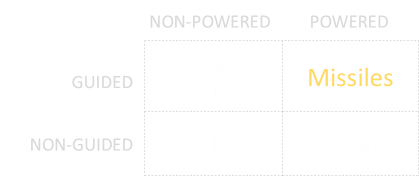
The simple answer is that a missile has a guidance system to allow it to steer and change course towards its intended target, and also a propulsion system that self drives it.

Munitions that are not self-powered and have no self-guidance are things like bullets, arrows, darts, artillery shells and cannon shot. Old school conventional bombs aka dumb-bombs also fall into this category. Once fired they are at the mercy of gravity and other external forces like drag and wind.

Some projectiles can self-propel, such as those pushed by rockets or even small jet-engines. These might even have inertial or stability platforms to allow them to fly more predefined paths, but they can’t change course if their intended targets move.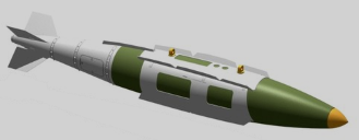
An additional class of weapons can change direction, but are not powered. These are typically released from planes, then drop down, changing course as needed through either GPS or following laser designated signals. In modern times, ‘smart bomb’ kits have been retrofitted to conventional dumb ‘iron bombs’. These consist of steerable fins, and an optional intelligent sensing nose cone. A smart bomb becomes a (very inefficient) glider and steers itself to the target.
Missiles
Missiles have both propulsion systems and guidance systems.

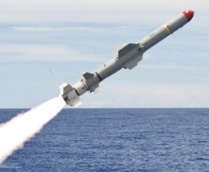
Image: Official US Naval ImageryMost missiles also contain a payload (typically an explosive warhead), and also a proximity fuze*. Contrary to what you might expect, a missile does not have to hit its target to explode. Especially in the province of an air target. Getting ‘close-enough’ is good enough to make an effective hit. Once the proximity fuze has triggered, the warhead explodes showering the target with thousands of pieces of very sharp, supersonic chunks of shrapnel complete with a pressure wave and lots of hot expanding gases. Aircraft are comprised of many delicate, balanced, and critical pieces of highly precision components (and often a couple of warm fleshy ones), typically protected by a very thin skin. Some of these components are rotating at high speed, and others can be very explosive. Some are needed to control and stabilize the aircraft. Damaging to even a small number of these essential components can critically harm the target and effectively destroy it.
*In common vernacular “FUZE” is used to identify complex trigger mechanisms and “FUSE” is reserved for a simple burning trigger.
Not all missiles have proximity fuzes, some are intended to hit their target. These transfer their kinetic energy directly to the target, acting more like large guided bullets. These are usually smaller in size (not needing an explosive warhead), but need to be more accurate. A very fast moving chunk of metal is going to do serious damage as it passes through a target, even if it does not explode!
It’s possible to go the other way too and make a large missile with a larger warhead that has an effective destructive radius that is much greater. With a larger explosive payload the definition of “close enough” gets less precise.
Ordnance History
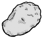
Long ago, if you wanted to hurt someone or something, you might have thrown a rock at them. The bigger the rock, and the faster you can thrown it, the more energy you can impart on your target.Higher speed is triply good; it allows you to throw the rock a further distance, and the energy carried by the rock is proportional to the speed squared. Finally, a faster speed means your rock gets to the target quicker and there is less chance it will have moved since launch!
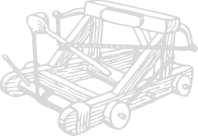
Soon, machines were designed to throw rocks for people. These allowed heavier rocks to do thrown, and also at greater speeds. They also provided some degree of control; They could be coarsely adjusted to aim for their intended target by pointing them roughly in the right direction, and adjusting the tension of the launch mechanism (or adjusting the mass of the projectile).

All these devices, however, are still essentially just ballistic devices. And, after launch, there was no control over the destiny of the projectile. You’d give it momentum and it would then be at the mercy of gravity and other aerodynamic forces. With the invention of gunpowder, cannon could be made. Cannon b***s travel much faster than slung rocks and so have much more destructive energy. They still suffered from accuracy problems. Two identical shots fired directly after each other with the same conditions would not necessarily hit the same locations.Early guns and muskets used round shot (miniature cannon b***s) and with tolerance limitations these shot were smaller in diameter than their barrels. As they were fired, they rattled down the barrel giving them unpredictability in their path after release. Once they left the barrel, they also drifted through the air in irregular ways depending on their spin. They were not very accurate.

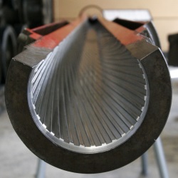
Accuracy was greatly improved by rifling the barrel of the gun. Rifling involves the cutting of helical grooves down the length of the barrel. A tightly fitting bullet is imparted spin as it is accelerated down the barrel. This spinning provides gyroscopic stability. Bullets also became more aerodynamically shaped.
Bullets were integrated into complete cartridges which provided casing, propellent, and a primer in one package. Improvements in propellants (creating higher pressure behind the bullet) and longer barrels (for more acceleration before exiting the gun), produced impressive muzzle velocities. Modern guns are pretty efficient machines, and at short to medium distances they are very effective.
Hey, keep still I’m trying to shoot you!Bullets can travel fast, but sometimes that is not fast enough. It takes time for the bullet to leave the gun and reach the target. During that time, the target could have moved,
If the target is moving in a very predictable and defined way it might be possible to ‘lead in’ and fire to where the target will be by the time the bullets get there. This technique is known very well to fighter pilots who give it the term Deflective Shooting.
This is also why, in American Football, Quarterbacks throw the ball ahead of the running receivers. They throw the ball to where the receiver will be when the ball arrives.
Stop jerking around, I’m still trying to shoot you!

Typically, the people you are trying to shoot want to avoid being shot and take evasive manoeuvres! They are not going to fly in straight lines or in predictable fashion. They are going to jinx, turn, feint, make random steering changes, adjust their speed and generally squirrel around.(There can also be other factors outside of your control affecting accuracy. For instance, there could be additional wind forces acting on the bullets. Tolerances in manufacture might mean that the bullets don’t always fly in the same path. Even if a shot is lined up, the bullets might not make their expected target).
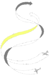
The ultimate solution would be to have the projectiles find the target themselves (bypassing external dependencies, randomness and unpredictable target manoeuvring). We’re now getting in the the territory of missiles. It would be nice to fire our weapon towards a target, and the weapon itself chase the target until sufficiently close to do the damage needed.Missiles
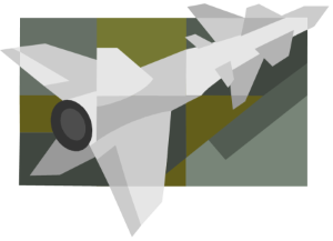
We’ve now reached the point of understanding why missiles are so important in modern warfare: Many targets are dynamic and move. To take down a random moving target requires an ordnance that is smart enough to manoeuvre, follow, chase and hopefully get close enough to cause damage. However, the verbs “follow” and “chase” hide quite a lot of subtly in implementation, as we will see …Over the years, more and more sophisticated systems have been developed to implement guidance control rules. In roughly chronological order, and complexity are:
1.Line of sight
2.Pure Pursuit
3.Proportional Navigation
Line of sight
This is a very simple control system and relies on the use of a base station that is constantly tracking the target.
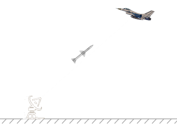
In Line of sight guidance, there is a reference point (in this case depicted by a ground radar station, but it could be a moving platform). Radiating out from this reference point is a beam pointing at the target. In LOS guidance, control signals are sent to the missile to keep it on this beam.If the missile stays on the beam pointed at the target, and has sufficient fuel and a fast enough relative speed, it will attain the target.
Course deviations are given to the the missile in the form of lateral acceleration requests (steering commands), to attempt to keep the perpendicular distance from the beam to zero.
There are two sub-classes of LOS, and these are CLOS (Command Line Of Sight) and BR (Beam Rider). In CLOS, the reference point is tracking both the target and the missile. Command signals are sent directly to the missile through some communications channel (either radio, or through a paid out thin umbilical cable that streams out behind the launched missile). These command signals give the course correction signals for the required lateral manoeuvres. This was is the control method that the first generation of guided missiles used. The disadvantages of this system are obvious: Constant communication between the missile and the ground station are required, and the reference station has to keep tracking both the target and the missile. The brains of the missile reside in the tracking station.
With BR guidance, the tracking station paints the target with some signal (typically a laser) and the missile uses onboard sensors (optical in the case of lasers), to ensure it stays riding along the middle of the beam. A BR missile does not require signals from the tracking station, and in this configuration, the tracking station only needs to track the target.
It’s not a requirement for the reference point and the missile launch site to be in the same location. The launched missile will follow its control law and quickly minimize the perpendicular distance to the Line of Sight.
Limitations of LOS
As mentioned earlier LOS was the control law used in the first generation of guided missiles, and it works reasonable well on targets that are not using excessive evading manoeuvres. As we will see later, however, as the missile gets closer, if the target is manoeuvring aggressively, high lateral acceleration requests are needed to keep it pointing at the target. It’s possible for these requests to exceed the limitations of the weapon, and if that happens the missile will overshoot and miss.
This can also occur when the target is approaching the reference point directly, as in the diagram below. The missile heads towards the target, constantly turning and pointing at it. As the target passes overhead, the missile needs to make tighter and tighter angular accelerations to continue pointing at the target. Eventually it may reach its turn limit and cannot turn any faster. If this happens, because of its speed, it will overshoot the target.
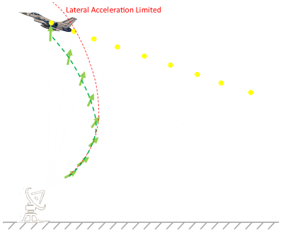
Because of the constant tracking needed by a reference station, LOS missiles can never reach the “Fire and Forget” sophistication level. If the reference platform is also moving (for instance if the reference platform is on another plane), then it will need to keep orientated vaguely in the direction of the target (until it is destroyed) in order to continue tracking the missile. This is not desirable in a combat situation.
Pure Pursuit
Pure Pursuit reduces the number of involved actors from three (reference point, missile, target) to just two (missile and target). In Pure Pursuit, the missile autonomously tracks the target and chases it directly, attempting to point at it the entire time.
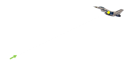
There are actually two variants of this control law, one is Attitude Pursuit, and the other is Velocity Pursuit. In AP, it is the axis of the missile that is kept pointing at the target. In VP, the missile’s velocity vector is the thing aimed at the target. These two are typically different vectors because the angle of attack of the missile is not aligned with the axis of the missile as it flies and skids across the sky. (It is VP that appears to perform better in real life.)
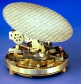
In the head of the missile is some kind of sensor array that is used to track the target (for instance an Infra Red optical sensor for a heat seeking missile). This is mounted on a gimbal, and moves to orient the array with the target. In simple AP law, the angle the sensor points away from the missile axis is the angle used to correct the course to point at the target. (In VP a vane on the side of the missile is also used to determine the direction the missile is traveling through the air).
Pure Pursuit guidance laws suffer the same late-stage extreme lateral acceleration request issues that LOS laws experience (especially when pointed at a target that is travelling towards the radar, rather than a tail-chase).Deviated Pursuit
Rather than pointing directly at the target, in an attempt to reduce the chance of getting into lateral acceleration limit (as outlined above), a technique called deviated pursuit can be employed. This is similar to the deflective shooting technique described that fighter pilots and quarterbacks use to lead-in to their targets. With a deviated pursuit control law, the steering commands request the missile be pointed a (fixed) couple of degrees ahead of the aiming angle. This helps point the missile to a location where the target shortly will be, and attempts to steer the missile based on knowledge of the targets path; this helps reduce chances of needing extreme lateral acceleration requests.
Gimbal limits

With guided missiles, it’s not just the physical limitations of the turn radius of the missile (which can be incredibly high), it’s the limitations of the sensor cradle too. The sensor gimbal has a maximum arc of sweep over which it can move to track the target, and also a maximum rate at which it is able swivel to keep the target in view. If the target can manoeuvre outside the sensor cone, it can ‘disappear’ from view.
A pure pursuit control law is like a predator chasing a prey in the animal world. For this reason, it is sometimes described as a ‘hound-hare pursuit’ and also as a scopodrome [skopien = to observe, dromos = act of running]. It typically results in a tail chase.
There’s a hole branch of mathematics dedicated to pursuit curves and the loci of their paths. The curves have interesting patterns depending on the ratio of their relative speeds, the distances apart, the lateral acceleration limits of each entity, and the style of the evasive manoeuvres taken by the target.
Proportional Navigation
The next level of sophistication in guidance is called Proportional Navigation. To understand Proportional Navigation we need to look at the concept known to mariners of Constant Bearing Angle (Decreasing Range).
Ships at sea are constantly worried about collisions with other ships. It’s good to know when there is a potential for this so that evasive manoeuvres can be taken. Just because the paths of two ships will cross, it does not mean that a collision will occur. For a collision, both ships must be in the same location at the same time. Paths have to cross for a collision to be possible, and the relative speeds are important to determine if both entities will arrive at the cross over point at the same time.

There are many ways to think about this. If you imagine you are on one of the ships, set this as your reference platform, and subtract your velocity from the other ship, you get the other ships velocity relative to you. It’s as is you are standing still, and the other ship is moving. If the relative velocity of the other ship brings it on a vector directly towards you, it means a collision will happen.Another way to imagine this is two cars racing down roads to a cross-road junction (or other intersection). Both could be travelling at different speeds. Will they collide?
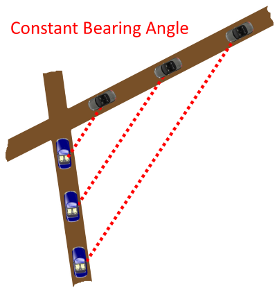
Imagine you are the passenger in one of the cars looking out the window. As you look out the window and spot the other car you might find that something interesting happens. If the other car keeps the same position out of the window as you race along, a collision will happen. If the angle of the other car to you gets tighter over time. it’s going to pass the intersection before you. If it gets wider, you’ll cross before it.If the angle remains constant, there is trouble ahead!
This is what sailors have known about for centuries. If you spot a ship on the horizon, and measure your bearing to it, then wait a little while and take a second bearing, and it is the same, then watch out, you are on a collision course (The caveat is that the ship also has to be getting bigger too! Hence the additional requirement of ‘Decreasing Range’. If the ship is getting smaller, it means it’s heading directly away from the potential collision point!)
If there is no relative velocity between two entities perpendicular to their LOS (and the entities are approaching each other), then a collision will occur!
What is bad for sailors (and reckless car drivers) is good for missiles …
Proportional Navigation
If a missile keeps on a trajectory with a constant bearing angle to the target, then it is sure to eventually hit the target. It does not chase or follow the target. What it does is fly a path that will place it in the same location as the target some time in the future.
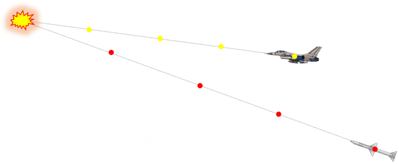
PN law uses the idea that if the LOS rate at any time is non-zero then the guidance command applied should be such that it annuls the LOS rate. In fact the lateral acceleration generated is made proportional to the LOS rate and the closing velocity. The scaling coefficient multiplying the error term is usually given a value between 3 and 5 (read a more advanced text book for why this range of values is appropriate).A PN guidance system has many advantages. It avoids potentially large lateral acceleration demands as it is not required to tail-chase the target, and has the potential to attain it’s target with less fuel expended than a system which tail chases (giving it a more effective range). If the target makes evasive manoeuvres, a PN missile can take corrective action by turning to keep the bearing angle constant; when this happens, the angular acceleration required by the missile is less because of its distance away from the target.
A PN law can almost be thought of as a ‘far sighted’ algorithm as it attempts to take corrective action right from launch. If fired at a non-manoeuvring target, then pretty much as soon as launched, it is quickly set up for a hit solution and no other guidance adjustments are needed for the rest of the flight (save for some minor tweaks), this improves reliability and hit success. As we saw above, the less sophisticated guidance laws require the highest acceleration manoeuvres right before impact!
To an external observer, a PN launched missile might look a little strange (especially if the target is heading towards the launcher). Rather than aiming at the target, the missile might leave the launcher in the opposite direction expected! (in the same direction as the target) As the target flies overhead, it will set up a course with constant LOS bearing angle, and simply fly into the target.
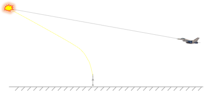
If you were on the target aircraft looking out, you would never see the missile pointing at you (as you would for the other control schemes). Instead, you would observe the missile streaking out to a not quite parallel point which you were also flying towards.It’s not all roses. Whilst a vanilla PN algorithm accounts for the target velocity and uses this to determine the collision point, it does not take into account the acceleration of the target (changing of speed along its path). The basic PN is also very sensitive to sensor noise. There are various enhanced versions of the PN algorithm that add in a measured acceleration term from the target. These algorithms are given the name Augmented Proportional Navigation guidance systems. APN algorithms attempt to ensure that all the large lateral accelerations required occur early on in the flight. (A further optimization described by the phrase Modern Guidance System, or MGS attempts to minimize all the lateral accelerations required over the entire flight. Every time an angular correction is needed, control surfaces need to be deflected. This causes drag, and drag both reduces the speed of the missile and it’s effective range).
Real Missiles
The above descriptions give a very simplistic view for how missile guidance works. In reality, there are three separate phases that a missile goes through. These phases are boost, midcourse, and terminal. There are separate guidance laws for each phase.
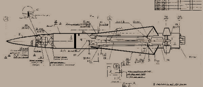
In the boost phase, the missile is accelerating up to speed at which it can be controlled (this may be performed by an expendable secondary stage). The launcher might also have some input as to the azimuth and elevation from which the missile is initially launched. For aircraft launched missiles, an added complication is to make sure the missile engine, when ignited, does not damage the launching aircraft!In the midcourse phase the missile might still be guided by external control (or not in the case of an autonomous missile).
The terminal phase (homing phase) is where the missile tries to get as close as possible to the target.
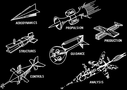
It’s more than just guidance
Finally, this article was just a basic introduction into guidance systems of missiles. Missiles, however, are very complex dynamic machines requiring skills in many disciplines.
They are precision devices that need to fly, be stable, be controlled, be lightweight, have good speed, be extremely manoeuvrable, not break apart with the stress of flight and launch, be reliable, have long shelf life, effective at destroying a target, cope with the stress of hanging off a pylon of a manoeuvring plane, be function at a wide range of temperature conditions, detect and track targets, not be spoofed by decoys, chaff and noise …
They also need cool names.
本文转自http://www.datagenetics.com/blog/august22014/index.html
-
走在地平线机器人之前的人工智能创业公司——深鉴科技发布在 行业动态
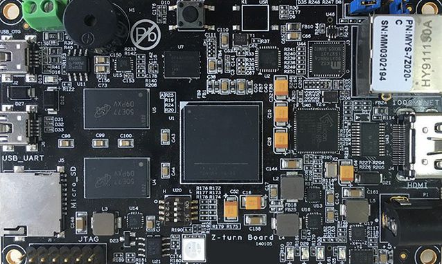
深鉴科技FPGA平台DPU产品开发板就在昨天(美国当地时间5月18日)举办的2016谷歌I/O 开发者大会上,在介绍完一系列应用及产品后,谷歌CEO桑达尔·皮查伊(Sundar Pichai)发布了专门为机器学习而打造的硬件“张量处理单元”( Tensor Processing Unit,TPU)。虽然皮查伊并未明确解释TPU是基于何种平台,但业内人士从已经公布的数据,比如散热器尺寸、开发周期、性能指标等推测,也能对TPU的技术原理略知一二了。可见,在服务器端使用专用硬件来支持深度学习相关应用已是大势所趋。
编者按:ICLR(the International Conference on Learning Representations)大会是近年来在深度学习领域影响力飙升的行业会议,旨在讨论如何更好的学习有意义、有价值的数据,从而应用于视觉、音频和自然语言处理等领域。大会联合主席为深度学习领军人物Yoshua Bengio和Yann LeCun。
在2016 年5月举办的ICLR大会上,有两篇论文获得了“2016年ICLR最佳论文”奖。一篇来自AlphaGo开发者谷歌DeepMind,另一篇则来自深鉴科技首席科学家韩松,他在论文中解释了如何利用“深度压缩”(Deep Compression)技术,将神经网络压缩数十倍而不影响准确度,从而降低计算复杂度和存储空间。
韩松所在的深鉴科技(Deephi Tech)成立于今年2月,专注于深度学习处理器与编译器技术,希望让每一台智能终端与云服务器都具有高性能、低功耗的深度学习计算能力。这家成立不久的科技初创公司目前已获得金沙江创投与高榕资本的天使轮融资。
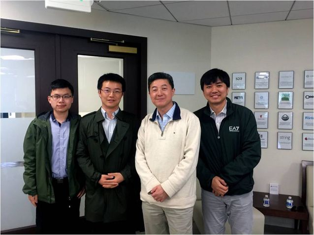
深鉴科技创始团队与著名华裔物理学家张首晟的合影。左起为姚颂、韩松、张首晟、汪玉进入正题之前,首先需要说明一个基本概念:FPGA(现场可编程门阵列,Field-Programmable Gate Array)。简而言之,这是一种程序驱动逻辑器件,就像一个微处理器,其控制程序存储在内存中,加电后,程序自动装载到芯片执行(该解释来自于中国科协“科普中国”)。
相比CPU和GPU,FPGA凭借比特级细粒度定制的结构、流水线并行计算的能力和高效的能耗,在深度学习应用中展现出独特的优势,在大规模服务器部署或资源受限的嵌入式应用方面有巨大潜力。此外,FPGA架构灵活,使得研究者能够在诸如GPU的固定架构之外进行模型优化探究。
众所周知,在深度神经网络计算中运用CPU、GPU已不是什么新鲜事。虽然Xilinx公司早在1985年就推出了第一款FPGA产品XC2064,但该技术真正应用于深度神经网络还是近几年的事。英特尔167亿美元收购Altera,IBM与Xilinx的合作,都昭示着FPGA领域的变革,未来也将很快看到FPGA与个人应用和数据中心应用的整合。
目前的FPGA市场由Xilinx和Altera主导,两者共同占有85%的市场份额。此外,FPGA正迅速取代ASIC和应用专用标准产品(ASSP)来实现固定功能逻辑。 FPGA市场规模预计在2016年将达到100亿美元。
深鉴科技创始人兼CEO姚颂对DT君表示,现在有很多公司在做各种各样的算法,包括ADAS(高级驾驶辅助系统)或者机器人等应用,因为算法是最快的切入方式。但算法最终要落地,无论是在CPU上运行,还是在GPU上运行,都会受限于性能、功耗和成本等因素。深鉴科技的产品将以ASIC级别的功耗,来达到优于GPU的性能,可把它称作“深度学习处理单元”(Deep Processing Unit,DPU),而第一批产品,将会基于FPGA平台。
他同时指出,深鉴科技目前的开发板功耗在4瓦左右,能够做到比一个15至20瓦的GPU性能高出两倍。而为了让所有做算法的人能够更加便捷地使用他们的产品,只有芯片肯定不行,所以他们也开发了自己的指令集和编译器。“相当于原来是先训练一个算法,然后再编译到CPU或GPU上运行,现在你也可以通过我们的编译器,把训练好的算法编译到DPU就可以直接运行了,在同样的开发周期内,获得相对于GPU一个数量级的能效提升。”
专访深鉴科技创始人兼CEO姚颂,这也是该公司第一次公开接受专访,全文如下,由“DeepTech深科技”编辑整理。
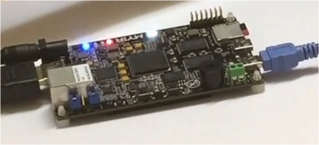
深鉴科技FPGA平台DPU产品开发板Q:DPU作为一个你们提出的新概念,其被认可程度如何?
姚颂:学术方面,ICLR 2016评选了两篇最佳论文,一篇是我们的《深度压缩:通过剪枝、受训量化和霍夫曼编码压缩深度神经网络》(Deep Compression: Compressing Deep Neural Networks With Pruning,Trained Quantization And Huffman Coding)。另一篇是谷歌DeepMind的《神经编程解释器》(Neural Programmer-Interpreters)。作为一个初创公司能拿到这个奖,对我们的激励是非常大的。我们的一系列论文也发表在NIPS 2015,FPGA 2016,ISCA 2016,这样一些在机器学习、计算机体系结构领域的最顶级会议上。
产业方面,今年二月份我们与全球最大的FPGA芯片制造商赛灵思(Xilinx)进行了交流,也与其他专注深度学习系统的硅谷公司进行了技术上的对比。之后,在OpenPOWER2016峰会中,赛灵思在讲到未来使用FPGA作为神经网络处理器加速标准时,所用的到的技术方面的PPT都是直接引用我们的公司的核心技术PPT,包括压缩以及卷积神经网络的硬件结构等。
相较于学术界的肯定,能被世界上最大的FPGA厂商认可并推广,更是一件令人振奋的事情。公司和清华的一篇合作论文也被半导体工业界的顶级会议Hot Chips 2016录用。
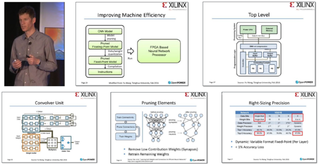
赛灵思 CTO 办公室的杰出工程师 Ralph Wittig 在 2016 年OpenPOWER峰会上的演讲Q:以前我们也有很多算法,但都是针对CPU和GPU,为什么深度学习出现后,你们会想到提出DPU这个新概念?
姚颂:首先是因为深度学习算法可以实用了,如果这个算法之前的精确度不足以实用,那么也没有必要专门开发DPU。另外,我们能够通过一个通用性的处理器来支持它,因为通用的神经网络基本上就是卷积层、非线性层、池化层,哪怕网络结构不同,最底层也还是这些基本单元。那么,一个支持这些底层操作的较为通用的处理器单元是可以满足这种要求的。
好比最开始我们需要运行一些程序,所以需要CPU;后来大家开始玩游戏,发现CPU满足不了3D渲染的需要,所以又加入了GPU。但如果深度学习技术像图形显示一样成为主流,大家都要具备智能计算的能力,将有一款专门的产品来替代,这是毫无疑问的。
Q:目前产品与主流CPU、GPU相比,具体性能表现如何?
姚颂:深度学习算法分为训练(Training)和应用(Inference)两部分。GPU平台并行度非常之高,在算法训练上非常高效,但在应用时,一次性只能对于一张输入图像进行处理,并行度的优势就不能完全发挥出来了。DPU只用于应用,也就是Inference阶段。目前基于FPGA的DPU产品可以实现相对于GPU有1个数量级的能效提升。
如在服务器端,我们基于FPGA的DPU板卡能够做到以更低的成本、低80%的功耗,实现多线程神经网络计算任务延迟降低数倍。而且兼容现有服务器与机房,可以实现即插即用。嵌入式端,DPU系统同样可以在降低80%功耗的情况下取得比GPU更好的性能。
而且从产品开发周期、迭代速度、生产成本、利用率方面来看,DPU产品虽然依托于FPGA平台,但是利用抽象出了指令集与编译器,可以快速开发、快速迭代,与专用的FPGA加速器产品相比,也具有非常明显的优势。
Q:DPU的瓶颈在哪里?
姚颂:DPU专门针对于深度学习算法设计,其应用范围只能是深度学习算法,而不像CPU与GPU那样通用。因此,在一些应用场景中,需要以DPU为核心,辅之以非机器学习或者非深度学习的方式相结合来打造完整系统。以手势检测为例,手的检测任务可以DPU运行深度学习算法来检测,但检测之后,判断手势速度我们会依赖摄像头和物体之间的几何关系求得,这一步就需要依赖于传统的方法了。当然,能否让用户用得习惯也是需要努力突破的地方,所以我们在一键生成指令上进行了很大的努力。
Q: FPGA平台的最大好处是什么?
姚颂:FPGA平台自身有三大优势:
首先是可编程,深度学习算法还未完全稳定,若深度学习算法发生大的变化,需要调整DPU架构,能够更新FPGA所搭载的DPU,适应最新的变化;
第二是高性能、低功耗。一方面,FPGA上可以进行比特级的细粒度优化,同时有十万级甚至更多执行单元并行处理,通过定制体系结构避免了通用处理器的冗余周期;另一方面,FPGA结构非常规整,相比于ASIC芯片可以享受最新的集成电路制造工艺带来的性能和功耗优势;
最后是高可靠性。FPGA有工业级与军工级芯片,都经过极低温与极高温下计算的苛刻测试,可以在各种环境下长时间稳定工作。
Q:深鉴科技开发的神经网络系统技术与全球比较知名的,如高通的Zeroth和IBM的TrueNorth相比,有什么特点?
姚颂:概念上和做法上都完全不一样。Zeroth和TrueNorth都是SNN,即Spiking Neural Networks,而现在实用的都是“卷积神经网络”( Convolutional Neural Networks,CNN),或者“深度神经网络”(Deep Neural Networks,DNN),在神经网络上有本质的区别。著名的AlphaGo即使用CNN来对场上局面进行分析。

最经典的卷积神经网络(CNN)AlexNet结构示意图
Q:CNN和SNN的本质区别是什么?两者又有何优劣?
姚颂:CNN的神经元向后传递一个数值,下一层直接依赖于上一层输出的数值进行计算;SNN的神经元向后传播一个脉冲序列,不是单个数值。举一个简单的例子,CNN里面每个数都可以是一个16比特的数,SNN用16个时钟周期发16个脉冲来表示这个数。
CNN本质是生物启发的计算模型,并非是脑科学的模型。而SNN更好的模拟了人的神经网络,更加的“类脑”,有更强的生物学基础,可能具有非常大的潜力。但是在目前,CNN的训练手段比较成熟,在实际的问题上可以达到很高的精确度,而SNN的训练方法不成熟,也因此暂时应用于大规模的识别问题还比较困难。
Q:深鉴科技目前做出的产品主要在致力于解决哪些问题?
姚颂:我们主要解决了以下几个方面的难点:首先是分析方面,研究与分析深度学习算法的计算与存储上的特征(Pattern)。
其次是设计方面,利用这些深度学习算法的特征,设计针对于神经网络的压缩方法、设计DPU体系结构、并且设计对应指令集,使得DPU能够支持各类深度学习算法。
第三是应用方面,打通从算法到硬件的全流程,用软硬件协同设计达到最好效果,并且开发好用的压缩编译工具,让所有人都能够方便的使用DPU产品。
最后是协同优化与迭代,针对实际应用的算法模型,进行DPU体系结构的评估,发现算法中不适合加速部分,再对于算法与体系结构进行优化或调整,使得应用中全系统性能进一步提升。
Q:目前你们的产品所做的计算都是基于本地的么?
姚颂:对于嵌入式端,目前在无人机,以及ADAS上的应用是不能依赖于网络的,因为对于延迟的要求非常的高。现在要么是CPU,要么是GPU,前者计算能力不够,后者功耗太高。那么我们和很多公司讨论的结果是FPGA是一个很好的方向。而云端的计算平台,也是DPU产品应用的很好场景。
Q:具体技术方面是否方便简要解释一下?
姚颂:“深度学习”这个概念大家进来听得耳朵都快起茧子了,它带来的好处咱们就不再赘述了。深度学习算法特点与传统计算有一个最大的区别,就是大规模数据复用。举个例子:在传统计算中,我们要计算A+B=C,会分别读取A、读取B,计算一次,得出C,然后A和B就可以放弃不用了,之后的计算用C就可以了。
神经网络就不是这样,比如在卷积神经网络中,一个卷积核要与特征图(Feature Map)进行多次卷积运算,是一种非常频繁反复的运算。每读取一张图,需要运算很多次,每读取一个卷积核,需要跟很多特征图发生多次卷积运算。
这种大规模重复运算中,如果每次都去读取数据会非常不高效,这也是为什么CPU和GPU不能高效运行深度学习算法的原因。CPU是读取数据,计算完毕后再写回去,而且由于本身计算单元较少,其性能就会被局限;GPU与CPU相比,拥有更多的ALU(算术逻辑单元),CPU的ALU比较少,而GPU则ALU非常多,比如Nvidia TK1就拥有192个核。但GPU上ALU附近的存储还是不够大,所以也摆脱不了读数-计算-写回这个过程,也导致了能耗一直下不去。
我们认为针对深度学习计算中的大规模频繁复用,应该有一种专用的内存结构,所以我们就设计了DPU。最早从2013年就开始做了,到2015年中,我们做出了学术版的DPU,从那时起,就一直在往产品成熟化的方向做。
Q:DPU的功耗、可靠性和兼容性怎么样?
姚颂:基于FPGA平台的DPU已经能够相对于GPU取得约一个数量级的更高的能效(Performance Per Watt),在DPU芯片制造后,能效指标能比现有FPGA平台产品再提升至少20倍。
可靠性上,我们的DPU已经经过长期测试,目前已经可以稳定运行,并且在超低温、超高温稳定工作,但是仍然需要更多的算法进行测试,来保证更高的可靠性。
兼容性上,深度学习算法尽管可以有各种各样的网络结构,但底层的运算都是一致的,包含卷积、全连接、非线性、池化等,因此该指令集兼容所有通用的深度学习算法。
Q:对于这种新的架构设计,用户端在转换平台时会不会有什么不适应?
姚颂:完全不会,最简单的使用流程是这样的:用户之前在GPU上训练一个算法,我们完全不干涉,当你训练完一个算法,会生成一个算法模型文件,来对这个神经网络进行表述。这个算法模型文件会交给我们的编译器,通过压缩和编译,得出的指令可以直接下载到FPGA上,就可以直接快速运行了。
Q:目前深鉴科技在产品方面是否有具体的计划?会主要针对那些领域?
姚颂:目前我们在着手打造无人机和服务器两个行业的两款核心产品。这两款产品不是小规模的概念性产品,而是可以大规模上线的商业级产品。应用领域将分为终端和云端两类。就终端市场而言,可能针对的领域包括ADAS、无人机、机器人,以及安防监控;云端市场将核心针对大型互联网公司的语音识别和图像处理,从云计算角度讲,如果能用DPU替换原有的CPU、GPU服务器,性能提升与功耗下降带来的益处将是巨大的。
Q:深鉴科技未来会侧重硬件开发还是提供解决方案?
姚颂:我们定位在深度学习平台公司,公司将以DPU为核心打造解决方案,不仅仅是提供芯片,而是提供行业内的整体的接口和SDK,方便所有人使用。我们的目标是不仅打造最好的深度学习处理器技术,也要打造最好用的解决方案和最高效的整体系统。
Q:国内外目前在做类似DPU概念和产品的比较优秀的团队还有哪些?
姚颂:国内目前有中科院陈云霁与陈天石老师,他们的“寒武纪”芯片设计也在一系列国际顶级会议发表。前百度深度学习研究院创始人余凯老师创办的地平线机器人科技,以及比特大陆、云天励飞等公司也在做积极的尝试。整体人工智能硬件的市场还在培育,我们也是希望大家一起让这个方向成为主流。
本文转自http://mittr.baijia.baidu.com/article/462202
-
opencv中IplImage, CvMat, Mat 数据结构的使用简介发布在 技术交流
本文转自http://www.cnblogs.com/summerRQ/articles/2406109.html
opencv中常见的与图像操作有关的数据容器有Mat,cvMat和IplImage,这三种类型都可以代表和显示图像,但是,Mat类型侧重于计算,数学性较高,openCV对Mat类型的计算也进行了优化。而CvMat和IplImage类型更侧重于“图像”,opencv对其中的图像操作(缩放、单通道提取、图像阈值操作等)进行了优化。在opencv2.0之前,opencv是完全用C实现的,但是,IplImage类型与CvMat类型的关系类似于面向对象中的继承关系。实际上,CvMat之上还有一个更抽象的基类----CvArr,这在源代码中会常见。
1. IplImage
opencv中的图像信息头,该结构体定义:
typedef struct _IplImage
{
    int nSize;    /* IplImage大小 */
    int ID;    /* 版本 (=0)*/
    int nChannels;  /* 大多数OPENCV函数支持1,2,3 或 4 个通道 */
    int alphaChannel;  /* 被OpenCV忽略 */
    int depth;   /* 像素的位深度: IPL_DEPTH_8U, IPL_DEPTH_8S, IPL_DEPTH_16U,
                IPL_DEPTH_16S, IPL_DEPTH_32S, IPL_DEPTH_32F and IPL_DEPTH_64F 可支持 */

    char colorModel[4]; /* 被OpenCV忽略 */
    char channelSeq[4]; /* 被OpenCV忽略 */
    int dataOrder;      /* 0 - 交叉存取颜色通道, 1 - 分开的颜色通道. cvCreateImage只能创建交叉存取图像 */
    int origin;     /* 0 - 顶—左结构,1 - 底—左结构 (Windows bitmaps 风格) */
    int align;     /* 图像行排列 (4 or 8). OpenCV 忽略它,使用 widthStep 代替 */

    int width;     /* 图像宽像素数 */
    int height;    /* 图像高像素数*/

    struct _IplROI *roi;  /* 图像感兴趣区域. 当该值非空只对该区域进行处理 */
    struct _IplImage *maskROI; /* 在 OpenCV中必须置NULL */
    void *imageId;  /* 同上*/
    struct _IplTileInfo *tileInfo;  /*同上*/

    int imageSize;    /* 图像数据大小(在交叉存取格式下imageSize=image->height*image->widthStep),单位字节*/
    char *imageData;    /* 指向排列的图像数据 */
    int widthStep;     /* 排列的图像行大小,以字节为单位 */
    int BorderMode[4];     /* 边际结束模式, 被OpenCV忽略 */
    int BorderConst[4];    /* 同上 */

    char *imageDataOrigin;    /* 指针指向一个不同的图像数据结构(不是必须排列的),是为了纠正图像内存分配准备的 */
} IplImage;
dataOrder中的两个取值:交叉存取颜色通道是颜色数据排列将会是BGRBGR…的交错排列。分开的颜色通道是有几个颜色通道就分几个颜色平面存储。roi是IplROI结构体,该结构体包含了xOffset,yOffset,height,width,coi成员变量,其中xOffset,yOffset是x,y坐标,coi代表channel of interest(感兴趣的通道),非0的时候才有效。访问图像中的数据元素,分间接存储和直接存储,当图像元素为浮点型时,(uchar *) 改为 (float *):
/*间接存取*/
IplImage* img=cvLoadImage("lena.jpg", 1);
CvScalar s;       /*sizeof(s) == img->nChannels*/
s=cvGet2D(img,i,j);  /*get the (i,j) pixel value*/
cvSet2D(img,i,j,s);   /*set the (i,j) pixel value*/

/*宏操作*/
IplImage* img; //malloc memory by cvLoadImage or cvCreateImage
for(int row = 0; row < img->height; row++)
{
    for (int col = 0; col < img->width; col++)
    {
        b = CV_IMAGE_ELEM(img, UCHAR, row, col * img->nChannels + 0);
        g = CV_IMAGE_ELEM(img, UCHAR, row, col * img->nChannels + 1);
        r = CV_IMAGE_ELEM(img, UCHAR, row, col * img->nChannels + 2);
    }
}

/*直接存取*/
IplImage* img; //malloc memory by cvLoadImage or cvCreateImage
uchar b, g, r; // 3 channels
for(int row = 0; row < img->height; row++)
{
    for (int col = 0; col < img->width; col++)
    {
        b = ((uchar *)(img->imageData + row * img->widthStep))[col * img->nChannels + 0];
        g = ((uchar *)(img->imageData + row * img->widthStep))[col * img->nChannels + 1];
        r = ((uchar *)(img->imageData + row * img->widthStep))[col * img->nChannels + 2];
    }
}
初始化使用IplImage *,是一个指向结构体IplImage的指针:
IplImage * cvLoadImage(const char * filename, int iscolor CV_DEFAULT(CV_LOAD_IMAGE_COLOR)); //load images from specified image
IplImage * cvCreateImage(CvSize size, int depth, int channels);  //allocate memory
2.CvMat
首先,我们需要知道,第一,在OpenCV中没有向量(vector)结构。任何时候需要向量,都只需要一个列矩阵(如果需要一个转置或者共轭向量,则需要一个行矩阵)。第二,OpenCV矩阵的概念与我们在线性代数课上学习的概念相比,更抽象,尤其是矩阵的元素,并非只能取简单的数值类型,可以是多通道的值。CvMat 的结构:
typedef struct CvMat
{
    int type;
    int step;          /*用字节表示行数据长度*/
    int* refcount;     /*内部访问*/
    union {
        uchar*  ptr;
        short*  s;
        int*    i;
        float*  fl;
        double* db;
    } data;    /*数据指针*/
     union {
        int rows;
        int height;
    };
    union {
        int cols;
        int width;
    };
} CvMat; /*矩阵结构头*/
创建CvMat数据:
CvMat * cvCreateMat(int rows, int cols, int type); /*创建矩阵头并分配内存*/
CV_INLine CvMat cvMat((int rows, int cols, int type, void* data CV_DEFAULT); /*用已有数据data初始化矩阵*/
CvMat * cvInitMatHeader(CvMat * mat, int rows, int cols, int type, void * data CV_DEFAULT(NULL), int step CV_DEFAULT(CV_AUTOSTEP)); /*(用已有数据data创建矩阵头)*/
对矩阵数据进行访问:
/*间接访问*/
/*访问CV_32F1和CV_64FC1*/
cvmSet( CvMat* mat, int row, int col, double value);
cvmGet( const CvMat* mat, int row, int col );

/*访问多通道或者其他数据类型: scalar的大小为图像的通道值*/
CvScalar cvGet2D(const CvArr * arr, int idx0, int idx1); //CvArr只作为函数的形参void cvSet2D(CvArr* arr, int idx0, int idx1, CvScalar value);

/*直接访问: 取决于数组的数据类型*/
/*CV_32FC1*/
CvMat * cvmat = cvCreateMat(4, 4, CV_32FC1);
cvmat->data.fl[row * cvmat->cols + col] = (float)3.0;

/*CV_64FC1*/
CvMat * cvmat = cvCreateMat(4, 4, CV_64FC1);
cvmat->data.db[row * cvmat->cols + col] = 3.0;

/*一般对于单通道*/
CvMat * cvmat = cvCreateMat(4, 4, CV_64FC1);
CV_MAT_ELEM(*cvmat, double, row, col) = 3.0; /*double是根据数组的数据类型传入,这个宏不能处理多通道*/

/*一般对于多通道*/
if (CV_MAT_DEPTH(cvmat->type) == CV_32F)
    CV_MAT_ELEM_CN(*cvmat, float, row, col * CV_MAT_CN(cvmat->type) + ch) = (float)3.0; // ch为通道值
if (CV_MAT_DEPTH(cvmat->type) == CV_64F)
    CV_MAT_ELEM_CN(*cvmat, double, row, col * CV_MAT_CN(cvmat->type) + ch) = 3.0; // ch为通道值

/*多通道数组*/
/*3通道*/
for (int row = 0; row < cvmat->rows; row++)
{
    p = cvmat ->data.fl + row * (cvmat->step / 4);
    for (int col = 0; col < cvmat->cols; col++)
    {
         *p = (float) row + col;
         *(p+1) = (float)row + col + 1;
         *(p+2) = (float)row + col + 2;
         p += 3;
    }
}
/*2通道*/
CvMat * vector = cvCreateMat(1,3, CV_32SC2);CV_MAT_ELEM(*vector, CvPoint, 0, 0) = cvPoint(100,100);
/*4通道*/
CvMat * vector = cvCreateMat(1,3, CV_64FC4);CV_MAT_ELEM(*vector, CvScalar, 0, 0) = CvScalar(0, 0, 0, 0);
复制矩阵操作:
/*复制矩阵*/
CvMat* M1 = cvCreateMat(4,4,CV_32FC1);
CvMat* M2;
M2=cvCloneMat(M1);
3.Mat
Mat是opencv2.0推出的处理图像的新的数据结构,现在越来越有趋势取代之前的cvMat和lplImage,相比之下Mat最大的好处就是能够更加方便的进行内存管理,不再需要程序员手动管理内存的释放。opencv2.3中提到Mat是一个多维的密集数据数组,可以用来处理向量和矩阵、图像、直方图等等常见的多维数据。
class CV_EXPORTS Mat
{

public:

/*..很多方法..*/
/*............*/

int flags;(Note :目前还不知道flags做什么用的)
int dims;  /*数据的维数*/
int rows,cols; /*行和列的数量;数组超过2维时为(-1,-1)*/
uchar *data;   /*指向数据*/
int * refcount;   /*指针的引用计数器; 阵列指向用户分配的数据时,指针为 NULL


/* 其他成员 */

};
从以上结构体可以看出Mat也是一个矩阵头,默认不分配内存,只是指向一块内存(注意读写保护)。初始化使用create函数或者Mat构造函数,以下整理自opencv2.3.1 Manual:
Mat(nrows, ncols, type, fillValue]);
M.create(nrows, ncols, type);

例子:
Mat M(7,7,CV_32FC2,Scalar(1,3)); /*创建复数矩阵1+3j*/
M.create(100, 60, CV_8UC(15)); /*创建15个通道的8bit的矩阵*/

/*创建100*100*100的8位数组*/
int sz[] = {100, 100, 100};
Mat bigCube(3, sz, CV_8U, Scalar:all(0));

/*现成数组*/
double m[3][3] = {{a, b, c}, {d, e, f}, {g, h, i}};
Mat M = Mat(3, 3, CV_64F, m).inv();

/*图像数据*/
Mat img(Size(320,240),CV_8UC3);
Mat img(height, width, CV_8UC3, pixels, step); /*const unsigned char* pixels,int width, int height, int step*/

/*使用现成图像初始化Mat*/
IplImage* img = cvLoadImage("greatwave.jpg", 1);
Mat mtx(img,0); // convert IplImage* -> Mat; /*不复制数据,只创建一个数据头*/
访问Mat的数据元素:
/*对某行进行访问*/
Mat M;
M.row(3) = M.row(3) + M.row(5) * 3; /*第5行扩大三倍加到第3行*/

/*对某列进行复制操作*/
Mat M1 = M.col(1);
M.col(7).copyTo(M1); /*第7列复制给第1列*/

/*对某个元素的访问*/
Mat M;
M.at<double>(i,j); /*double*/
M.at(uchar)(i,j);  /*CV_8UC1*/
Vec3i bgr1 = M.at(Vec3b)(i,j) /*CV_8UC3*/
Vec3s bgr2 = M.at(Vec3s)(i,j) /*CV_8SC3*/
Vec3w bgr3 = M.at(Vec3w)(i,j) /*CV_16UC3*/

/*遍历整个二维数组*/
double sum = 0.0f;
for(int row = 0; row < M.rows; row++)
{
    const double * Mi = M.ptr<double>(row);
    for (int col = 0; col < M.cols; col++)
        sum += std::max(Mi[j], 0.);
}

/*STL iterator*/
double sum=0;
MatConstIterator<double> it = M.begin<double>(), it_end = M.end<double>();
for(; it != it_end; ++it)
sum += std::max(*it, 0.);
Mat可进行Matlab风格的矩阵操作,如初始化的时候可以用initializers,zeros(), ones(), eye(). 除以上内容之外,Mat还有有3个重要的方法:
Mat mat = imread(const String* filename);           // 读取图像
imshow(const string frameName, InputArray mat);  //    显示图像
imwrite (const string& filename, InputArray img);    //储存图像
4. CvMat, Mat, IplImage之间的互相转换
IpIImage -> CvMat /*cvGetMat*/ CvMat matheader; CvMat * mat = cvGetMat(img, &matheader); /*cvConvert*/ CvMat * mat = cvCreateMat(img->height, img->width, CV_64FC3); cvConvert(img, mat) IplImage -> Mat Mat::Mat(const IplImage* img, bool copyData=false);/*default copyData=false,与原来的IplImage共享数据,只是创建一个矩阵头*/ 例子: IplImage* iplImg = cvLoadImage("greatwave.jpg", 1); Mat mtx(iplImg); /* IplImage * -> Mat,共享数据; or : Mat mtx = iplImg;*/ Mat -> IplImage Mat M IplImage iplimage = M; /*只创建图像头,不复制数据*/ CvMat -> Mat Mat::Mat(const CvMat* m, bool copyData=false); /*类似IplImage -> Mat,可选择是否复制数据*/ Mat -> CvMat 例子(假设Mat类型的imgMat图像数据存在): CvMat cvMat = imgMat;/*Mat -> CvMat, 类似转换到IplImage,不复制数据只创建矩阵头 -
行人检测资源(下)代码数据发布在 技术交流
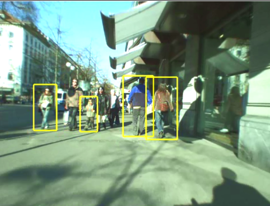
这是行人检测相关资源的第二部分:源码和数据集。考虑到实际应用的实时性要求,源码主要是C/C++的。源码和数据集的网址,经过测试都可访问,并注明了这些网址最后更新的日期,供学习和研究进行参考。(欢迎补充更多的资源)1 Source Code
1.1 INRIA Object Detection and Localization Toolkit
http://pascal.inrialpes.fr/soft/olt/
Dalal于2005年提出了基于HOG特征的行人检测方法,行人检测领域中的经典文章之一。HOG特征目前也被用在其他的目标检测与识别、图像检索和跟踪等领域中。
更新:2008
1.2 Real-time Pedestrian Detection.
http://cs.nju.edu.cn/wujx/projects/C4/C4.htm
Jianxin Wu实现的快速行人检测方法。
Real-Time Human Detection Using Contour Cues:
http://c2inet.sce.ntu.edu.sg/Jianxin/paper/ICRA_final.pdf
更新:2012
1.3 霍夫变换实现的多目标检测
http://graphics.cs.msu.ru/en/science/research/machinelearning/hough
Olga Barinova, CVPR 2010 Paper: On detection of multiple object instances using Hough Transforms
源码:C++
更新:2010
1.4 HIKSVM
http://ttic.uchicago.edu/~smaji/projects/fiksvm/
Classification Using Intersection Kernel SVMs is efficient
HOG+LBP+HIKSVM, 行人检测的经典方法.
源码:C/C++
更新:2012
1.5 GroundHOG
http://www.mmp.rwth-aachen.de/projects/groundhog
GPU-based Object Detection with Geometric Constraints, In: ICVS, 2011. CUDA版本的HOG+SVM,
源码:C/C++
更新:2011
1.6 doppia code
https://bitbucket.org/rodrigob/doppia
这是一个代码集合,包含如下:
Pedestrian detection at 100 frames per second, R. Benenson. CVPR, 2012. 实时的
Stixels estimation without depth map computation
Fast stixels estimation for fast pedestrian detection
Seeking the strongest rigid detector
Ten years of pedestrian detection, what have we learned?
Face detection without bells and whistles
源码:C/C++
更新:2015
1.7 Multiple camera pedestrian detection.
POM: Occupancy map estimation for people detection
http://cvlab.epfl.ch/software/pom/
Paper:Multi-Camera People Tracking with a Probabilistic Occupancy Map
源码:?
更新:2014
1.8 Pitor Dollar Detector.
Piotr’s Computer Vision Matlab Toolbox
http://vision.ucsd.edu/~pdollar/toolbox/doc/index.html
The toolbox is divided into 7 parts, arranged by directory:
channels Robust image features, including HOG, for fast object detection.
classify Fast clustering, random ferns, RBF functions, PCA, etc.
detector Aggregate Channel Features (ACF) object detection code.
filters Routines for filtering images.
images Routines for manipulating and displaying images.
matlab General Matlab functions that should have been a part of Matlab.
videos Routines for annotating and displaying videos.
源码:matlab
更新:2014
2 DataSets
2.1 MIT数据库
http://cbcl.mit.edu/software-datasets/PedestrianData.html
介绍:该数据库为较早公开的行人数据库,共924张行人图片(ppm格式,宽高为64×128),肩到脚的距离约80象素。该数据库只含正面和背面两个视角,无负样本,未区分训练集和测试集。Dalal等采用“HOG+SVM”,在该数据库上的检测准确率接近100%。
更新:2000
2.2 INRIA Person Dataset
http://pascal.inrialpes.fr/data/human/
介绍:该数据库是“HOG+SVM”的作者Dalal创建的,该数据库是目前使用最多的静态行人检测数据库,提供原始图片及相应的标注文件。训练集有正样本614张(包含2416个行人),负样本1218张;测试集有正样本288张(包含1126个行人),负样本453张。图片中人体大部分为站立姿势且高度大于100个象素,部分标注可能不正确。图片主要来源于GRAZ-01、个人照片及google,因此图片的清晰度较高。在XP操作系统下部分训练或者测试图片无法看清楚,但可用OpenCV正常读取和显示。
更新:2005
2.3 Daimler行人数据库
http://www.gavrila.net/Research/Pedestrian_Detection/Daimler_Pedestrian_Benchmark_D/
该数据库采用车载摄像机获取,分为检测和分类两个数据集。检测数据集的训练样本集有正样本大小为18×36和48×96的图片各15560(3915×4)张,行人的最小高度为72个象素;负样本6744张(大小为640×480或360×288)。测试集为一段27分钟左右的视频(分辨率为640×480),共21790张图片,包含56492个行人。分类数据库有三个训练集和两个测试集,每个数据集有4800张行人图片,5000张非行人图片,大小均为18×36,另外还有3个辅助的非行人图片集,各1200张图片。
更新:2009?
2.4 Caltech Pedestrian Detection
http://www.vision.caltech.edu/Image_Datasets/CaltechPedestrians/
该数据库是目前规模较大的行人数据库,采用车载摄像头拍摄,约10个小时左右,视频的分辨率为640×480,30帧/秒。标注了约250,000帧(约137分钟),350000个矩形框,2300个行人,另外还对矩形框之间的时间对应关系及其遮挡的情况进行标注。数据集分为set00~set10,其中set00~set05为训练集,set06~set10为测试集(标注信息尚未公开)。性能评估方法有以下三种:(1)用外部数据进行训练,在set06~set10进行测试;(2)6-fold交叉验证,选择其中的5个做训练,另外一个做测试,调整参数,最后给出训练集上的性能;(3)用set00~set05训练,set06~set10做测试。由于测试集的标注信息没有公开,需要提交给Pitor Dollar。结果提交方法为每30帧做一个测试,将结果保存在txt文档中(文件的命名方式为I00029.txt I00059.txt ……),每个txt文件中的每行表示检测到一个行人,格式为“[left, top,width, height, score]”。如果没有检测到任何行人,则txt文档为空。该数据库还提供了相应的Matlab工具包,包括视频标注信息的读取、画ROC(Receiver Operatingcharacteristic Curve)曲线图和非极大值抑制等工具。
更新:2014
2.5 TUD行人数据库
https://www.mpi-inf.mpg.de/departments/multi-cue-onboard-pedestrian-detection/
介绍:TUD行人数据库为评估运动信息在行人检测中的作用,提供图像对以便计算光流信息。训练集的正样本为1092对图像(图片大小为720×576,包含1776个行人);负样本为192对非行人图像(手持摄像机85对,车载摄像机107对);另外还提供26对车载摄像机拍摄的图像(包含183个行人)作为附加训练集。测试集有508对图像(图像对的时间间隔为1秒,分辨率为640×480),共有1326个行人。Andriluka等也构建了一个数据库用于验证他们提出的检测与跟踪相结合的行人检测技术。该数据集的训练集提供了行人的矩形框信息、分割掩膜及其各部位(脚、小腿、大腿、躯干和头部)的大小和位置信息。测试集为250张图片(包含311个完全可见的行人)用于测试检测器的性能,2个视频序列(TUD-Campus和TUD-Crossing)用于评估跟踪器的性能。
更新:2010
2.6 NICTA行人数据库
http://www.nicta.com.au/category/research/computer-vision/tools/automap-datasets/
该数据库是目前规模较大的静态图像行人数据库,25551张含单人的图片,5207张高分辨率非行人图片,数据库中已分好训练集和测试集,方便不同分类器的比较。Overett等用“RealBoost+Haar”评估训练样本的平移、旋转和宽高比等各种因素对分类性能的影响:(1)行人高度至少要大于40个象素;(2)在低分辨率下,对于Haar特征来说,增加样本宽度的性能好于增加样本高度的性能;(3)训练图片的大小要大于行人的实际大小,即背景信息有助于提高性能;(4)对训练样本进行平移提高检测性能,旋转对性能的提高影响不大。以上的结论对于构建行人数据库具有很好的指导意义。
更新:2008
2.7 ETHZ行人数据库
Robust Multi-Person Tracking from Mobile Platforms
https://data.vision.ee.ethz.ch/cvl/aess/dataset/
Ess等构建了基于双目视觉的行人数据库用于多人的行人检测与跟踪研究。该数据库采用一对车载的AVT Marlins F033C摄像头进行拍摄,分辨率为640×480,帧率13-14fps,给出标定信息和行人标注信息,深度信息采用置信度传播方法获取。
更新:2010
2.8 CVC行人数据库
http://www.cvc.uab.es/adas/site/?q=node/7
该数据库目前包含三个数据集(CVC-01、CVC-02和CVC-Virtual),主要用于车辆辅助驾驶中的行人检测研究。CVC-01[Geronimo,2007]有1000个行人样本,6175个非行人样本(来自于图片中公路区域中的非行人图片,不像有的行人数据库非行人样本为天空、沙滩和树木等自然图像)。CVC-02包含三个子数据集(CVC-02-CG、CVC-02-Classification和CVC-02-System),分别针对行人检测的三个不同任务:感兴趣区域的产生、分类和系统性能评估。图像的采集采用Bumblebee2立体彩色视觉系统,分辨率640×480,焦距6mm,对距离摄像头0~50m的行人进行标注,最小的行人图片为12×24。CVC-02-CG主要针对候选区域的产生,有100张彩色图像,包含深度和3D点信息;CVC-02-Classification主要针对行人分类,训练集有1016张正样本,7650张负样本,测试集分为基于切割窗口的分类(570张行人,7500张非行人)和整张图片的检测(250张包含行人的图片,共587个行人);CVC-02-System主要用于系统的性能评估,包含15个视频序列(4364帧),7983个行人。CVC-Virtual是通过Half-Life 2图像引擎产生的虚拟行人数据集,共包含1678虚拟行人,2048个非行人图片用于测试。
更新:2015,目前已经更新到CVC-08了。
2.9 USC行人数据库
http://iris.usc.edu/Vision-Users/OldUsers/bowu/DatasetWebpage/dataset.html
该数据库包含三组数据集(USC-A、USC-B和USC-C),以XML格式提供标注信息。USC-A[Wu, 2005]的图片来自于网络,共205张图片,313个站立的行人,行人间不存在相互遮挡,拍摄角度为正面或者背面;USC-B的图片主要来自于CAVIAR视频库,包括各种视角的行人,行人之间有的相互遮挡,共54张图片,271个行人;USC-C有100张图片来自网络的图片,232个行人(多角度),行人之间无相互遮挡。
更新:2007
3 其他资料
1:Video:Pedestrian Detection: The State of the Art
http://research.microsoft.com/apps/video/default.aspx?id=135046&r=1
A video talk byPitor Dollar. Pitor Dollar做了很多关于行人检测方法的研究,他们研究小组的Caltech Pedestrian Dataset也很出名。
2:Statistical and Structural Recognition of Human Actions. ECCV, 2010 Tutorial, by Ivan Laptev and Greg Mori. (注:要用爬墙软件才能访问到)
3: Human Action Recognition in realistic scenarios, 一份很好的硕士生毕业论文开题资料。
参考:http://hi.baidu.com/susongzhi/item/085983081b006311eafe38e7
参考:http://blog.csdn.net/dpstill/article/details/22420065
转载出处:http://www.cvrobot.net/pedestrian-detection-resource-2-code-and-dataset/
-
行人检测资源(上)综述文献发布在 技术交流
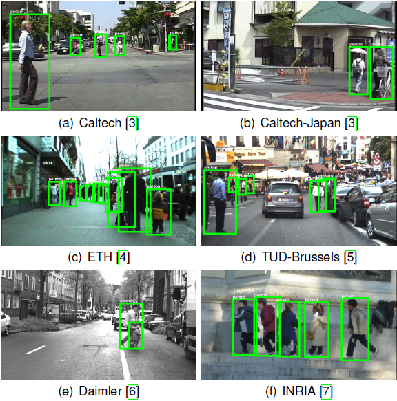
行人检测具有极其广泛的应用:智能辅助驾驶,智能监控,行人分析以及智能机器人等领域。从2005年以来行人检测进入了一个快速的发展阶段,但是也存在很多问题还有待解决,主要还是在性能和速度方面还不能达到一个权衡。近年,以谷歌为首的自动驾驶技术的研发正如火如荼的进行,这也迫切需要能对行人进行快速有效的检测,以保证自动驾驶期间对行人的安全不会产生威胁。1 行人检测的现状
大概可以分为两类1.1 基于背景建模
    利用背景建模方法,提取出前景运动的目标,在目标区域内进行特征提取,然后利用分类器进行分类,判断是否包含行人;背景建模目前主要存在的问题:

    1)必须适应环境的变化(比如光照的变化造成图像色度的变化);

    2)相机抖动引起画面的抖动(比如手持相机拍照时候的移动);

    3)图像中密集出现的物体(比如树叶或树干等密集出现的物体,要正确的检测出来);

    4)必须能够正确的检测出背景物体的改变(比如新停下的车必须及时的归为背景物体,而有静止开始移动的物体也需要及时的检测出来)。

    5)物体检测中往往会出现Ghost区域,Ghost区域也就是指当一个原本静止的物体开始运动,背静差检测算法可能会将原来该物体所覆盖的区域错误的检测为运动的,这块区域就成为Ghost,当然原来运动的物体变为静止的也会引入Ghost区域,Ghost区域在检测中必须被尽快的消除。
1.2 基于统计学习的方法
    这也是目前行人检测最常用的方法,根据大量的样本构建行人检测分类器。提取的特征主要有目标的灰度、边缘、纹理、颜色、梯度直方图等信息。分类器主要包括神经网络、SVM、adaboost以及现在被计算机视觉视为宠儿的深度学习。

    统计学习目前存在的难点:

    1)行人的姿态、服饰各不相同、复杂的背景、不同的行人尺度以及不同的光照环境。

    2)提取的特征在特征空间中的分布不够紧凑;

    3)分类器的性能受训练样本的影响较大;

    4)离线训练时的负样本无法涵盖所有真实应用场景的情况;

     目前的行人检测基本上都是基于法国研究人员Dalal在2005的CVPR发表的HOG+SVM的行人检测算法(Histograms of Oriented Gradients for Human Detection, Navneet Dalel,Bill Triggs, CVPR2005)。HOG+SVM作为经典算法也集成到opencv里面去了,可以直接调用实现行人检测

    为了解决速度问题可以采用背景差分法的统计学习行人检测,前提是背景建模的方法足够有效(即效果好速度快),目前获得比较好的检测效果的方法通常采用多特征融合的方法以及级联分类器。(常用的特征有Harry-like、Hog特征、LBP特征、Edgelet特征、CSS特征、COV特征、积分通道特征以及CENTRIST特征)。
2 综述类的文章
2.1 行人检测十年回顾
    Ten Years of Pedestrian Detection, What Have We Learned?

    一篇2014年ECCV的文章,是对pedestrian detectiond过去十年发展的回顾,从dataset,main approaches的角度分析了近10年的40多篇论文提出的方法,并对提高feature复杂度的影响进行了评估

    下载:http://rodrigob.github.io/documents/2014_eccvw_ten_years_of_pedestrian_detection_with_supplementary_material.pdf

    学习笔记:http://blog.csdn.net/mduke/article/details/46582443
2.2 P.Dollar PAMI 2012上的综述
    P.Dollar, C. Wojek,B. Schiele, et al. Pedestrian detection: an evaluation of the state of the art [J]. IEEE Transactions on Pattern Analysis and Machine Intelligence, 2012, 34(4): 743-761.

    2012年PAMI上发表的一篇关于行人检测的综述性文章,PDF格式,共20页,对常见的16种行人检测算法进行了简单描述,并在6个公开测试库上进行测试,给出了各种方法的优缺点及适用情况。另外,指出了未来行人检测的发展方向和趋势。

    下载:http://vision.ucsd.edu/~pdollar/files/papers/DollarPAMI12peds.pdf
2.3 CVPR2010 HOF和CSS
    https://www.d2.mpi-inf.mpg.de/CVPR10Pedestrians

    New Features and Insights for Pedestrian Detection

    文中使用改进的HOG,即HOF和CSS(color self similarity)特征,使用HIK SVM分类器。 本文的作者是德国人:Stefen Walk。目前Stefan Walk在苏黎世联邦理工大学任教。
2.4 Integral Channel Features
    加州理工学院2009年行人检测的文章:Integral Channel Features(积分通道特征)

    这篇文章与2012年PAMI综述文章是同一作者。作者:Piotr Dollar

    Paper下载:http://pages.ucsd.edu/~ztu/publication/dollarBMVC09ChnFtrs_0.pdf

    中文笔记:http://blog.csdn.net/carson2005/article/details/8455837
2.5 The Fastest Pedestrian Detector in the West
    Dollar 在 2010 年 BMVC 的 《The fastest pedestrian detector in the west》 一文中提出了一种新的思想,这种思想只需要训练一个标准 model,检测 N/K(K ≈10) 然后其余的 N-N/K 种大小的图片的特征不需要再进行这种复杂的计算,而是跟据这 N/K 次的结果, 由另外一种简单的算法给估计出来,这种思想实现的 基础是大小相近的图像的特征可以被足够精确的估计出来

    下载:http://vision.ucsd.edu/sites/default/files/FPDW_0.pdf
2.6 DPM算法做目标检测
    CVPR2008:A Discriminatively Trained, Multiscale, Deformable Part Model

    PAMI2010:Object Detection with Discriminatively Trained Part Based Models

    CVPR2010:Cascade Object Detection with Deformable Part Models

    以上三篇文章,都是作者研究DPM算法做目标检测的文章,有源代码可以下载。

    作者的个人主页:http://cs.brown.edu/~pff/papers/
2.7 利用DPM模型,检测粘连
    Detection and Tracking of Occluded People

    IJCV2014年的文章,利用DPM模型,检测粘连情况很严重的行人,效果很好。

    下载:http://www.bmva.org/bmvc/2012/BMVC/paper009/
2.8 UDN算法
    ICCV2013:

    1)Joint Deep Learning for Pedestrian Detection

    2)Multi-Stage Contextual Deep Learning for Pedestrian Detection

    简 称UDN算法,从文中描述的检测效果来看,该方法是所有方法中最好的,并且,效果远超过其他方法。经过对论文和该算法源码的研究,该算法是与作者另外一篇 论文的方法 ,另外的论文算法做图片扫描,得到矩形框,然后用该方法对矩形框进行进一步确认,以及降低误警率和漏警率。另外的论文是:Multi-Stage Contextual Deep Learning for Pedestrian Detection。

    这篇文章是用深度学习的CNN做candidate window的确认。而主要的行人检测的算法还是HOG+CSS+adaboost。

    香港中文大学,Joint Deep Learning for Pedestrian Detection,行人检测论文的相关资源:http://www.ee.cuhk.edu.hk/~wlouyang/projects/ouyangWiccv13Joint/index.html
2.9 Monocular pedestrian detection
     Enzweiler, and D.Gavrila. Monocular pedestrian detection: survey and experiments [J]. IEEE Transactions on Pattern Analysis and Machine Intelligence, 2009,  31(12): 2179-2195.

    下载:http://www.gavrila.net/pami09.pdf
2.10 Survey of pedestrian detection for advanced driver assistance systems
    Geronimo, A. M.Lopez and A. D. Sappa, et al. Survey of pedestrian detection for advanced driver assistance systems [J].  IEEE Transactionson Pattern Analysis and Machine Intelligence,  2010, 32(7): 1239-1258.

     百度文库下载:http://wenku.baidu.com/link?url=xLDWZTdLXT1_fiZoUzNFiyQtZTwnyL-lZHhTSI0B87vkIE6UEDrKz6iz8zpKmmPvZq7ktlX6WRxyVxcjk8B-ymgl53QBfzBEKgYPZmsi1l_
2.11 Vision-based Pedestrian Protection Systems for Intelligent Vehicles
    Geronimo, and A. M.Lopez. Vision-based Pedestrian Protection Systems for Intelligent Vehicles, BOOK, 2014.

    下载:http://bookzz.org/book/2167094/e21639
2.12 行人检测技术综述
    苏松志, 李绍滋, 陈淑媛等. 行人检测技术综述[J]. 电子学报, 2012, 40(4): 814-820.

    下载:行人检测技术综述
2.13 车辆辅助驾驶系统中基于计算机视觉的行人检测研究综述
    贾慧星, 章毓晋.车辆辅助驾驶系统中基于计算机视觉的行人检测研究综述[J], 自动化学报, 2007, 33(1): 84-90.

    下载:车辆辅助驾驶系统中基于计算机视觉的行人检测研究综述
2.14 行人检测系统研究新进展及关键技术展望
    许言午, 曹先彬,乔红. 行人检测系统研究新进展及关键技术展望[J], 电子学报, 2008, 36(5): 368-376.

    下载:行人检测系统研究新进展及关键技术展望
2.15 基于视觉的人的运动识别综述
     杜友田; 陈峰;徐文立; 李永彬;基于视觉的人的运动识别综述, 电子学报,  2007. 35(1): 84-90.

    下载:基于视觉的人的运动识别综述
2.16 基于机器学习的行人检测关键技术研究
朱文佳. 基于机器学习的行人检测关键技术研究[D]. 第一章, 硕士学位论文, 上海交通大学. 2008. 指导教师: 戚飞虎.参考:http://hi.baidu.com/susongzhi/item/085983081b006311eafe38e7
参考:http://blog.csdn.net/dpstill/article/details/22420065
声明:
本文来源:http://www.cvrobot.net/pedestrian-detection-resource-1-summary-review-survey/
-
实时SLAM的未来及与深度学习的比较发布在 技术交流
声明:本文转自http://www.computervisionblog.com/2016/01/why-slam-matters-future-of-real-time.html
Last month’s International Conference of Computer Vision (ICCV) was full of Deep Learning techniques, but before we declare an all-out ConvNet victory, let’s see how the other “non-learning” geometric side of computer vision is doing. SimultaneousLocalization and Mapping, or SLAM, is arguably one of the most important algorithms in Robotics, with pioneering work done by both computer vision and robotics research communities. Today I’ll be summarizing my key points from ICCV’s Future of Real-Time SLAM Workshop, which was held on the last day of the conference (December 18th, 2015).Today’s post contains a brief introduction to SLAM, a detailed description of what happened at the workshop (with summaries of all 7 talks), and some take-home messages from the Deep Learning-focused panel discussion at the end of the session.
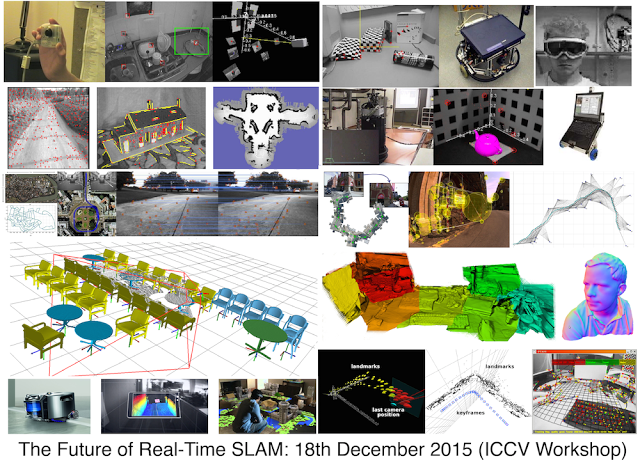
SLAM visualizations. Can you identify any of these SLAM algorithms?Part I: Why SLAM Matters
Visual SLAM algorithms are able to simultaneously build 3D maps of the world while tracking the location and orientation of the camera (hand-held or head-mounted for AR or mounted on a robot). SLAM algorithms are complementary to ConvNets and Deep Learning: SLAM focuses on geometric problems and Deep Learning is the master of perception (recognition) problems. If you want a robot to go towards your refrigerator without hitting a wall, use SLAM. If you want the robot to identify the items inside your fridge, use ConvNets.
Basics of SfM/SLAM: From point observation and intrinsic camera parameters, the 3D structure of a scene is computed from the estimated motion of the camera. For details, see openMVG website.
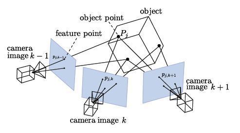
SLAM is a real-time version of Structure from Motion (SfM). Visual SLAM or vision-based SLAM is a camera-only variant of SLAM which forgoes expensive laser sensors and inertial measurement units (IMUs). Monocular SLAM uses a single camera while non-monocular SLAM typically uses a pre-calibrated fixed-baseline stereo camera rig. SLAM is prime example of a what is called a “Geometric Method” in Computer Vision. In fact, CMU’s Robotics Institute splits the graduate level computer vision curriculum into a Learning-based Methods in Vision course and a separate Geometry-Based Methods in Vision course.Structure from Motion vs Visual SLAM

Structure from Motion (SfM) and SLAM are solving a very similar problem, but while SfM is traditionally performed in an offline fashion, SLAM has been slowly moving towards the low-power / real-time / single RGB camera mode of operation. Many of the today’s top experts in Structure from Motion work for some of the world’s biggest tech companies, helping make maps better. Successful mapping products like Google Maps could not have been built without intimate knowledge of multiple-view geometry, SfM, and SLAM. A typical SfM problem is the following: given a large collection of photos of a single outdoor structure (like the Colliseum), construct a 3D model of the structure and determine the camera’s poses. The image collection is processed in an offline setting, and large reconstructions can take anywhere between hours and days.SfM Software: Bundler is one of the most successful SfM open source libraries
Here are some popular SfM-related software libraries:Bundler, an open-source Structure from Motion toolkit
Libceres, a non-linear least squares minimizer (useful for bundle adjustment problems)
Andrew Zisserman’s Multiple-View Geometry MATLAB FunctionsVisual SLAM vs Autonomous Driving
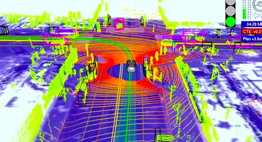
While self-driving cars are one of the most important applications of SLAM, according to Andrew Davison, one of the workshop organizers, SLAM for Autonomous Vehicles deserves its own research track. (And as we’ll see, none of the workshop presenters talked about self-driving cars). For many years to come it will make sense to continue studying SLAM from a research perspective, independent of any single Holy-Grail application. While there are just too many system-level details and tricks involved with autonomous vehicles, research-grade SLAM systems require very little more than a webcam, knowledge of algorithms, and elbow grease. As a research topic, Visual SLAM is much friendlier to thousands of early-stage PhD students who’ll first need years of in-lab experience with SLAM before even starting to think about expensive robotic platforms such as self-driving cars.
Part II: The Future of Real-time SLAM
Now it’s time to officially summarize and comment on the presentations from The Future of Real-time SLAM workshop. Andrew Davison started the day with an excellent historical overview of SLAM called 15 years of vision-based SLAM, and his slides have good content for an introductory robotics course.
For those of you who don’t know Andy, he is the one and only Professor Andrew Davison of Imperial College London. Most known for his 2003 MonoSLAM system, he was one of the first to show how to build SLAM systems from a single “monocular” camera at a time when just everybody thought you needed a stereo “binocular” camera rig. More recently, his work has influenced the trajectory of companies such as Dyson and the capabilities of their robotic systems (e.g., the brand new Dyson360).
I remember Professor Davidson from the Visual SLAM tutorial he gave at the BMVC Conference back in 2007. Surprisingly very little has changed in SLAM compared to the rest of the machine-learning heavy work being done at the main vision conferences. In the past 8 years, object recognition has undergone 2-3 mini revolutions, while today’s SLAM systems don’t look much different than they did 8 years ago. The best way to see the progress of SLAM is to take a look at the most successful and memorable systems. In Davison’s workshop introduction talk, he discussed some of these exemplary systems which were produced by the research community over the last 10-15 years:
MonoSLAM
PTAM
FAB-MAP
DTAM
KinectFusion
Davison vs Horn: The next chapter in Robot Vision
Davison also mentioned that he is working on a new Robot Vision book, which should be an exciting treat for researchers in computer vision, robotics, and artificial intelligence. The last Robot Vision book was written by B.K. Horn (1986), and it’s about time for an updated take on Robot Vision.

A new robot vision book?While I’ll gladly read a tome that focuses on the philosophy of robot vision, personally I would like the book to focus on practical algorithms for robot vision, like the excellent Multiple View Geometry book by Hartley and Zissermann orProbabilistic Robotics by Thrun, Burgard, and Fox. A “cookbook” of visual SLAM problems would be a welcome addition to any serious vision researcher’s collection.
Talk 1: Christian Kerl on Continuous Trajectories in SLAM
The first talk, by Christian Kerl, presented a dense tracking method to estimate a continuous-time trajectory. The key observation is that most SLAM systems estimate camera poses at a discrete number of time steps (either they key frames which are spaced several seconds apart, or the individual frames which are spaced approximately 1/25s apart).

Continuous Trajectories vs Discrete Time Points. SLAM/SfM usually uses discrete time points, but why not go continuous?
Much of Kerl’s talk was focused on undoing the damage of rolling shutter cameras, and the system demo’ed by Kerl paid meticulous attention to modeling and removing these adverse rolling shutter effects.
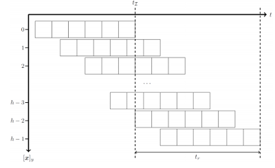
Undoing the damage of rolling shutter in Visual SLAM.Related: Kerl’s Dense continous-time tracking and mapping slides.
Related: Dense Continuous-Time Tracking and Mapping with Rolling Shutter RGB-D Cameras (C. Kerl, J. Stueckler, D. Cremers), In IEEE International Conference on Computer Vision (ICCV), 2015. [pdf]Talk 2: Semi-Dense Direct SLAM by Jakob Engel
LSD-SLAM came out at ECCV 2014 and is one of my favorite SLAM systems today! Jakob Engel was there to present his system and show the crowd some of the coolest SLAM visualizations in town. LSD-SLAM is an acronym for Large-Scale Direct Monocular SLAM. LSD-SLAM is an important system for SLAM researchers because it does not use corners or any other local features. Direct tracking is performed by image-to-image alignment using a coarse-to-fine algorithm with a robust Huber loss. This is quite different than the feature-based systems out there. Depth estimation uses an inverse depth parametrization (like many other SLAM systems) and uses a large number or relatively small baseline image pairs. Rather than relying on image features, the algorithms is effectively performing “texture tracking”. Global mapping is performed by creating and solving a pose graph “bundle adjustment” optimization problem, and all of this works in real-time. The method is semi-dense because it only estimates depth at pixels solely near image boundaries. LSD-SLAM output is denser than traditional features, but not fully dense like Kinect-style RGBD SLAM.
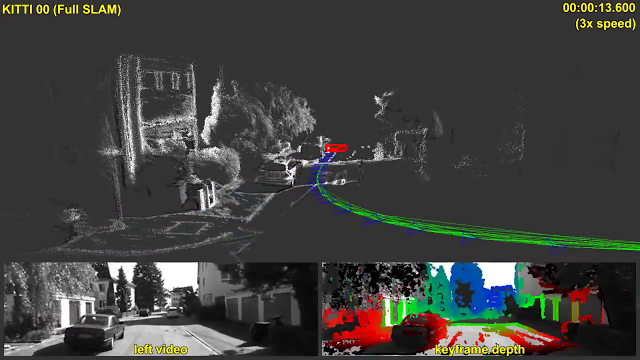
LSD-SLAM in Action: LSD-SLAM generates both a camera trajectory and a semi-dense 3D scene reconstruction. This approach works in real-time, does not use feature points as primitives, and performs direct image-to-image alignment.
Engel gave us an overview of the original LSD-SLAM system as well as a handful of new results, extending their initial system to more creative applications and to more interesting deployments. (See paper citations below)Related: LSD-SLAM Open-Source Code on github LSD-SLAM project webpage
Related: LSD-SLAM: Large-Scale Direct Monocular SLAM (J. Engel, T. Schöps, D. Cremers), In European Conference on Computer Vision (ECCV), 2014. [pdf] [video]
An extension to LSD-SLAM, Omni LSD-SLAM was created by the observation that the pinhole model does not allow for a large field of view. This work was presented at IROS 2015 (Caruso is first author) and allows a large field of view (ideally more than 180 degrees). From Engel’s presentation it was pretty clear that you can perform ballerina-like motions (extreme rotations) while walking around your office and holding the camera. This is one of those worst-case scenarios for narrow field of view SLAM, yet works quite well in Omni LSD-SLAM.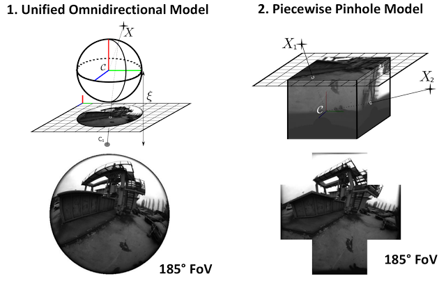
Related: Large-Scale Direct SLAM for Omnidirectional Cameras (D. Caruso, J. Engel, D. Cremers), In International Conference on Intelligent Robots and Systems (IROS), 2015. [pdf] [video]Stereo LSD-SLAM is an extension of LSD-SLAM to a binocular camera rig. This helps in getting the absolute scale, initialization is instantaneous, and there are no issues with strong rotation. While monocular SLAM is very exciting from an academic point of view, if your robot is a 30,000$ car or 10,000$ drone prototype, you should have a good reason to not use a two+ camera rig. Stereo LSD-SLAM performs quite competitively on SLAM benchmarks.
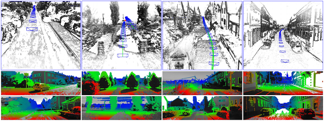
Stereo LSD-SLAM. Excellent results on KITTI vehicle-SLAM dataset.Stereo LSD-SLAM is quite practical, optimizes a pose graph in SE(3), and includes a correction for auto exposure. The goal of auto-exposure correcting is to make the error function invariant to affine lighting changes. The underlying parameters of the color-space affine transform are estimated during matching, but thrown away to estimate the image-to-image error. From Engel’s talk, outliers (often caused by over-exposed image pixels) tend to be a problem, and much care needs to be taken to care of their effects.Related: Large-Scale Direct SLAM with Stereo Cameras (J. Engel, J. Stueckler, D. Cremers), In International Conference on Intelligent Robots and Systems (IROS), 2015. [pdf] [video]
Later in his presentation, Engel gave us a sneak peak on new research about integrating both stereo and inertial sensors. For details, you’ll have to keep hitting refresh on Arxiv or talk to Usenko/Engel in person. On the applications side, Engel’s presentation included updated videos of an Autonomous Quadrotor driven by LSD-SLAM. The flight starts with an up-down motion to get the scale estimate and a free-space octomap is used to estimate the free-space so that the quadrotor can navigate space on its own. Stay tuned for an official publication…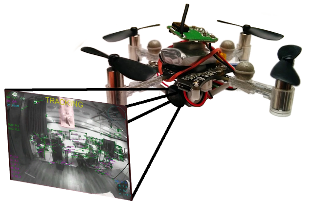
Quadrotor running Stereo LSD-SLAM.The story of LSD-SLAM is also the story of feature-based vs direct-methods and Engel gave both sides of the debate a fair treatment. Feature-based methods are engineered to work on top of Harris-like corners, while direct methods use the entire image for alignment. Feature-based methods are faster (as of 2015), but direct methods are good for parallelism. Outliers can be retroactively removed from feature-based systems, while direct methods are less flexible w.r.t. outliners. Rolling shutter is a bigger problem for direct methods and it makes sense to use a global shutter or a rolling shutter model (see Kerl’s work). Feature-based methods require making decisions using incomplete information, but direct methods can use much more information. Feature-based methods have no need for good initialization and direct-based methods need some clever tricks for initialization. There is only about 4 years of research on direct methods and 20+ on sparse methods. Engel is optimistic that direct methods will one day rise to the top, and so am I.
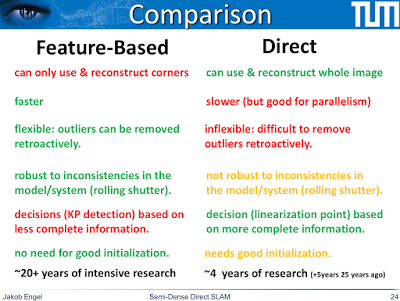
Feature-based vs direct methods of building SLAM systems. Slide from Engel’s talk.At the end of Engel’s presentation, Davison asked about semantic segmentation and Engel wondered whether semantic segmentation can be performed directly on semi-dense “near-image-boundary” data. However, my personal opinion is that there are better ways to apply semantic segmentation to LSD-like SLAM systems. Semi-dense SLAM can focus on geometric information near boundaries, while object recognition can focus on reliable semantics away from the same boundaries, potentially creating a hybrid geometric/semantic interpretation of the image.
Talk 3: Sattler on The challenges of Large-Scale Localization and Mapping
Torsten Sattler gave a talk on large-scale localization and mapping. The motivation for this work is to perform 6-dof localization inside an existing map, especially for mobile localization. One of the key points in the talk was that when you are using traditional feature-based methods, storing your descriptors soon becomes very costly. Techniques such as visual vocabularies (remember product quantization?) can significantly reduce memory overhead, and with clever optimization at some point storing descriptors no longer becomes the memory bottleneck.
Another important take-home message from Sattler’s talk is that the number of inliers is not actually a good confidence measure for camera pose estimation. When the feature point are all concentrated in a single part of the image, camera localization can be kilometers away! A better measure of confidence is the “effective inlier count” which looks at the area spanned by the inliers as a fraction of total image area. What you really want is feature matches from all over the image — if the information is spread out across the image you get a much better pose estimate.Sattler’s take on the future of real-time slam is the following: we should focus on compact map representations, we should get better at understanding camera pose estimate confidences (like down-weighing features from trees), we should work on more challenging scenes (such as worlds with planar structures and nighttime localization against daytime maps)
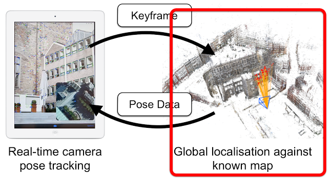
Mobile Localisation: Sattler’s key problem is localizing yourself inside a large city with a single smartphone pictureTalk 4: Mur-Artal on Feature-based vs Direct-Methods
Raúl Mur-Artal, the creator of ORB-SLAM, dedicated his entire presentation to the Feature-based vs Direct-method debate in SLAM and he’s definitely on the feature-based side. ORB-SLAM is available as an open-source SLAM package and it is hard to beat. During his evaluation of ORB-SLAM vs PTAM it seems that PTAM actually fails quite often (at least on the TUM RGB-D benchmark). LSD-SLAM errors are also much higher on the TUM RGB-D benchmark than expected.
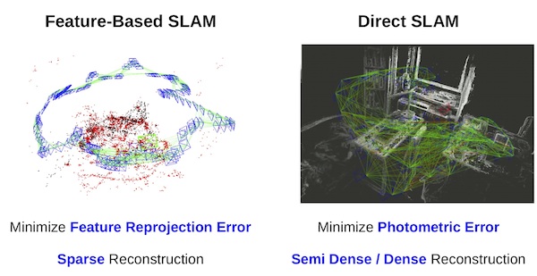
Talk 5: Project Tango and Visual loop-closure for image-2-image constraints
Simply put, Google’s Project Tango is the world’ first attempt at commercializing SLAM. Simon Lynen from Google Zurich (formerly ETH Zurich) came to the workshop with a Tango live demo (on a tablet) and a presentation on what’s new in the world of Tango. In case you don’t already know, Google wants to put SLAM capabilities into the next generation of Android Devices.
Google’s Project Tango needs no introduction.
The Project Tango presentation discussed a new way of doing loop closure by finding certain patters in the image-to-image matching matrix. This comes from the “Placeless Place Recognition” work. They also do online bundle adjustment w/ vision-based loop closure.
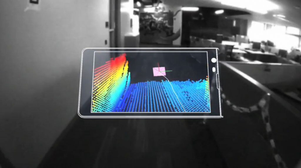
The Project Tango folks are also working on combing multiple crowd-sourced maps at Google, where the goals to combine multiple mini-maps created by different people using Tango-equipped devices.Simon showed a video of mountain bike trail tracking which is actually quite difficult in practice. The idea is to go down a mountain bike trail using a Tango device and create a map, then the follow-up goal is to have a separate person go down the trail. This currently “semi-works” when there are a few hours between the map building and the tracking step, but won’t work across weeks/months/etc.During the Tango-related discussion, Richard Newcombe pointed out that the “features” used by Project Tango are quite primitive w.r.t. getting a deeper understanding of the environment, and it appears that Project Tango-like methods won’t work on outdoor scenes where the world is plagued by non-rigidity, massive illumination changes, etc. So are we to expect different systems being designed for outdoor systems or will Project Tango be an indoor mapping device?
Talk 6: ElasticFusion is DenseSLAM without a pose-graph
ElasticFusion is a dense SLAM technique which requires a RGBD sensor like the Kinect. 2-3 minutes to obtain a high-quality 3D scan of a single room is pretty cool. A pose-graph is used behind the scenes of many (if not most) SLAM systems, and this technique has a different (map-centric) approach. The approach focuses on building a map, but the trick is that the map is deformable, hence the name ElasticFusion. The “Fusion” part of the algorithm is in homage to KinectFusion which was one of the first high quality kinect-based reconstruction pipelines. Also surfels are used as the underlying primitives.
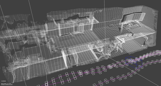
Image from Kintinuous, an early version of Whelan’s Elastic Fusion.Recovering light sources: we were given a sneak peak at new unpublished work from Imperial College London / dyson Robotics Lab. The idea is that detecting the light source direction and detecting specularities, you can improve 3D reconstruction results. Cool videos of recovering light source locations which work for up to 4 separate lights.
Related: Map-centric SLAM with ElasticFusion presentation slides
Related: ElasticFusion: Dense SLAM Without A Pose Graph. Whelan, Thomas and Leutenegger, Stefan and Salas-Moreno, Renato F and Glocker, Ben and Davison, Andrew J. In RSS 2015.Talk 7: Richard Newcombe’s DynamicFusion
Richard Newcombe’s (whose recently formed company was acquired by Oculus), was the last presenter. It’s really cool to see the person behind DTAM, KinectFusion, and DynamicFusion now working in the VR space.
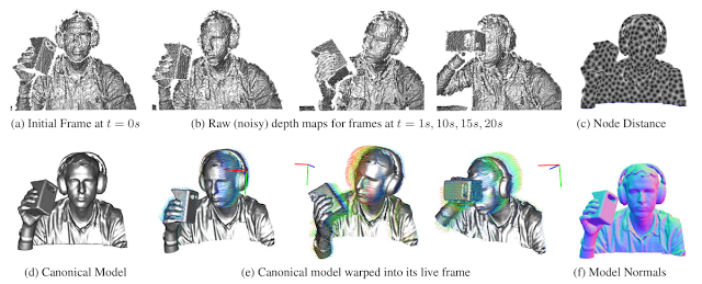
Related: SLAM++: Simultaneous Localisation and Mapping at the Level of Objects Renato F. Salas-Moreno, Richard A. Newcombe, Hauke Strasdat, Paul H. J. Kelly and Andrew J. Davison (CVPR 2013)
Related: KinectFusion: Real-Time Dense Surface Mapping and Tracking Richard A. Newcombe Shahram Izadi,Otmar Hilliges, David Molyneaux, David Kim, Andrew J. Davison, Pushmeet Kohli, Jamie Shotton, Steve Hodges, Andrew Fitzgibbon (ISMAR 2011, Best paper award!)Workshop Demos
During the demo sessions (held in the middle of the workshop), many of the presenter showed off their SLAM systems in action. Many of these systems are available as open-source (free for non-commercial use?) packages, so if you’re interested in real-time SLAM, downloading the code is worth a shot. However, the one demo which stood out was Andrew Davison’s showcase of his MonoSLAM system from 2004. Andy had to revive his 15-year old laptop (which was running Redhat Linux) to show off his original system, running on the original hardware. If the computer vision community is going to oneway decide on a “retro-vision” demo session, I’m just going to go ahead and nominate Andy for the best-paper prize, right now.
Andry’s Retro-Vision SLAM Setup (Pictured on December 18th, 2015)It was interesting to watch the SLAM system experts wave their USB cameras around, showing their systems build 3D maps of the desk-sized area around their laptops. If you carefully look at the way these experts move the camera around (i.e., smooth circular motions), you can almost tell how long a person has been working with SLAM. When the non-experts hold the camera, probability of tracking failure is significantly higher.
I had the pleasure of speaking with Andy during the demo session, and I was curious which line of work (in the past 15 years) surprised him the most. His reply was that PTAM, which showed how to perform real-time bundle adjustment, surprised him the most. The PTAM system was essentially a MonoSLAM++ system, but the significantly improved tracking results were due to taking a heavyweight algorithm (bundle adjustment) and making it real-time — something which Andy did not believe was possible in the early 2000s.
Part III: Deep Learning vs SLAM
The SLAM panel discussion was a lot of fun. Before we jump to the important Deep Learning vs SLAM discussion, I should mention that each of the workshop presenters agreed that semantics are necessary to build bigger and better SLAM systems. There were lots of interesting mini-conversations about future directions. During the debates, Marc Pollefeys (a well-known researcher in SfM and Multiple-View Geometry) reminded everybody that Robotics is the killer application of SLAM and suggested we keep an eye on the prize. This is quite surprising since SLAM was traditionally applied to Robotics problems, but the lack of Robotics success in the last few decades (Google Robotics?) has shifted the focus of SLAM away from Robots and towards large-scale map building (ala Google Maps) and Augmented Reality. Nobody at this workshop talked about Robots.
Integrating semantic information into SLAMThere was a lot of interest in incorporating semantics into today’s top-performing SLAM systems. When it comes to semantics, the SLAM community is unfortunately stuck in the world of bags-of-visual-words, and doesn’t have new ideas on how to integrate semantic information into their systems. On the other end, we’re now seeing real-time semantic segmentation demos (based on ConvNets) popping up at CVPR/ICCV/ECCV, and in my opinion SLAM needs Deep Learning as much as the other way around.
Integrating semantics into SLAM is often talk about, but it is easier said than done.
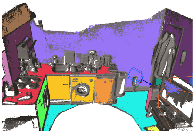
Figure 6.9 (page 142) from Moreno’s PhD thesis: Dense Semantic SLAM“Will end-to-end learning dominate SLAM?”
Towards the end of the SLAM workshop panel, Dr. Zeeshan Zia asked a question which startled the entire room and led to a memorable, energy-filled discussion. You should have seen the look on the panel’s faces. It was a bunch of geometers being thrown a fireball of deep learning. Their facial expressions suggest both bewilderment, anger, and disgust. “How dare you question us?” they were thinking. And it is only during these fleeting moments that we can truly appreciate the conference experience. Zia’s question was essentially: Will end-to-end learning soon replace the mostly manual labor involved in building today’s SLAM systems?.Zia’s question is very important because end-to-end trainable systems have been slowly creeping up on many advanced computer science problems, and there’s no reason to believe SLAM will be an exception. A handful of the presenters pointed out that current SLAM systems rely on too much geometry for a pure deep-learning based SLAM system to make sense — we should use learning to make the point descriptors better, but leave the geometry alone. Just because you can use deep learning to make a calculator, it doesn’t mean you should.

Learning Stereo Similarity Functions via ConvNets, by Yan LeCun and collaborators.
While many of the panel speakers responded with a somewhat affirmative “no”, it was Newcombe which surprisingly championed what the marriage of Deep Learning and SLAM might look like.Newcombe’s Proposal: Use SLAM to fuel Deep Learning
Although Newcombe didn’t provide much evidence or ideas on how Deep Learning might help SLAM, he provided a clear path on how SLAM might help Deep Learning. Think of all those maps that we’ve built using large-scale SLAM and all those correspondences that these systems provide — isn’t that a clear path for building terascale image-image “association” datasets which should be able to help deep learning? The basic idea is that today’s SLAM systems are large-scale “correspondence engines” which can be used to generate large-scale datasets, precisely what needs to be fed into a deep ConvNet.Concluding Remarks
There is quite a large disconnect between the kind of work done at the mainstream ICCV conference (heavy on machine learning) and the kind of work presented at the real-time SLAM workshop (heavy on geometric methods like bundle adjustment). The mainstream Computer Vision community has witnessed several mini-revolutions within the past decade (e.g., Dalal-Triggs, DPM, ImageNet, ConvNets, R-CNN) while the SLAM systems of today don’t look very different than they did 8 years ago. The Kinect sensor has probably been the single largest game changer in SLAM, but the fundamental algorithms remain intact. Integrating semantic information: The next frontier in Visual SLAM.

Today’s SLAM systems help machines geometrically understand the immediate world (i.e., build associations in a local coordinate system) while today’s Deep Learning systems help machines reason categorically (i.e., build associations across distinct object instances). In conclusion, I share Newcombe and Davison excitement in Visual SLAM, as vision-based algorithms are going to turn Augmented and Virtual Reality into billion dollar markets. However, we should not forget to keep our eyes on the “trillion-dollar” market, the one that’s going to redefine what it means to “work” — namely Robotics. The day of Robot SLAM will come soon.
-
基于TOF技术避障与物体3D模型构建发布在 技术交流
声明:本文转自http://www.csdn.net/article/a/2015-12-29/15833252
摘要:对于智能机器人,避障是一个不可或缺的功能,本文章提供一种基于TOF技术的红外避障方案,单芯片同时能够精准测距、3D图形构建、手势识别。距离远、精度高、延迟少。一、前言
对于智能机器人,避障是一个不可或缺的功能,本文章提供一种基于TOF技术的红外避障方案,单芯片同时能够精准测距、3D图形构建、手势识别。距离远、精度高、延迟少。
二、概述
TOF,即Time ON Fly,利用红外光在空气中的飞行时间,算出距离物体距离。
TOF测距距离远,精度高,相比超声波测距优势很大,同时多点感应的TOF芯片,比如88=64点感应的,更精确的有240320的,可以实现构建物体3D模型,应用非常广,比如扫描房间轮廓,构建地图、识别手势,可以在Dragon Board 410c DSP上定义各种手势代表意义,比目前常用手势识别IC智能识别上下左右前后等更灵活。
本文我们尝试基于Dragon Board 410c 去搭建一个TOF 8*8阵列的IC,型号为EPC610。
三、详细说明
3.1 TOF测距原理
利用红外光在空气中的飞行时间,算出距离物体距离

光的飞行时间:
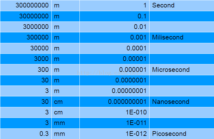
TOF距离测量
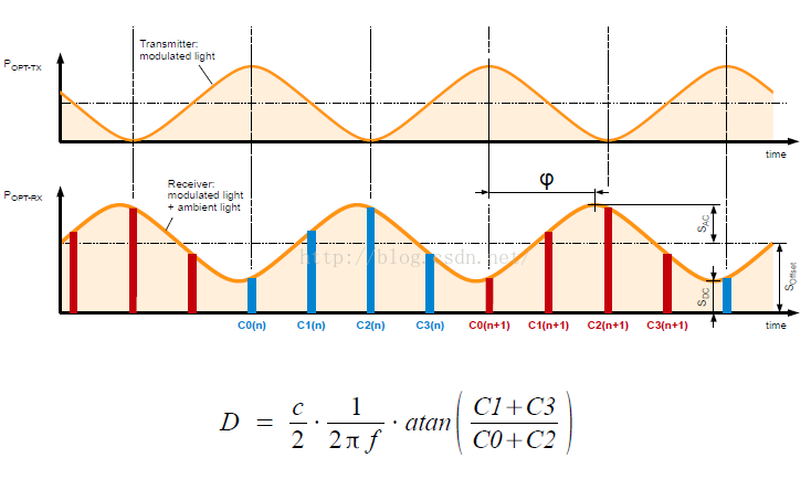
3.2 TOF系统测距的优势
3.2.1TOF优势
完整的图像采集
高帧频
距离的测量范围从几厘米到数十米
体积小,集成度高,周边器件少,高经济效益。
无移动部件
根据不同环境光自动调节
3.2.2TOF 8*8EPC610特点
片上全集成的距离测量或者物体检测数据采集系统,减少周边器件,使设计最简化。
片上集成高功率LED驱动
易于同微处理器组成相应的应用
绝对距离测量并以数据形式输出
片上集成数据信号处理
具有高灵敏度,并且测量距离最远可达15米(10MHZ)
响应时间可小于1ms
数字数据接口输出,包含12bit的距离数据以及4bit的信号质量等参数
优良的环境光抑制能力,最高可 >100kLux.
内部集成环境光检测能力 (“Luxmeter”)
例如:亮度控制或调光功能
+8.5V以及-3.0V电源供电以及非常低的电源功耗
数字数据接口 (2-wire / SPI)
SMD全兼容的超小CSP24芯片封装
3.3 基于Dragon Board 410cTOF测距应用设计
3.3.1通讯接口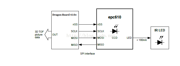
选用410C的SPI接口,但EPC610是5V的IO电平,需增加Level shift。
3.3.2设计注意事项
为获取更高的测量距离与误差,需注意以下:
如上图,增加聚光的镜头,同时为不让发射光直接被Sensor感知,镜头底座不漏光。
-5V的偏压峰值纹波要求比较高,-5V是由+5V经过chargepump反转的来的电压,注意不要跟其他模块共用。
3.3 总结
超声波测距对反射物体要求比较高,面积小的物体,如线、锥形物体就基本测不到,而TOF红外测距完全可克服此问题,同时TOF测距精度高,测距远,响应快。考虑到红外避障会受环境的影响,比如强太阳光下、大雾环境下、被测物体是透明玻璃,红外光直接透过等,因此我们推荐超声波与红外可搭配应用,互补各自缺点。
